DESCRIPTION |
DTC No. | DTC Detection Condition |
Trouble Area | | P106A |
The
pressure detected by the canister pressure sensor (Vapor Pressure
Pump*) and the pressure detected by the manifold absolute pressure
sensor (MAP*) differ by 7 kPa (54 mmHg) or more (2 trip detection logic) |
- Canister pressure sensor (canister pump module)
- Manifold absolute pressure sensor
| | P106B |
The
pressure detected by the canister pressure sensor (Vapor Pressure
Pump*) and the pressure detected by the pressure sensor of either air
switching valve (for Bank 1 or Bank 2) (Air Pump Pressure (Absolute)* or
Air Pump2 Pressure (Absolute)*) differ by 6.98 kPa (52 mmHg) or more (2 trip detection logic) |
- Canister pressure sensor (canister pump module)
- Air switching valve (Bank 1)
- Air switching valve (Bank 2)
| HINT: *: Name of Data List item MONITOR DESCRIPTION
This DTC is stored when a deviation from pressure sensor characteristics is detected.
The
pressure sensors* are checked 55 minutes after the ignition switch is
turned off. If the pressures detected by the pressure sensors* differ by
a certain amount, the MIL is illuminated and a DTC is stored (2 trip
detection logic).
HINT:
- *: P106A checks the canister pressure sensor and manifold absolute
pressure sensor. P106B checks the canister pressure sensor and the
pressure sensor of the air switching valves (Bank 1 and Bank 2).
- Correct judgment may not be possible when the altitude is 4000 m (13120 ft.) or more.
MONITOR STRATEGY |
Related DTCs | P106A: Evaporative emission system pressure sensor - manifold absolute pressure correlation
P106B: Evaporative emission system pressure sensor - secondary air injection system pressure sensor correlation | |
Required Sensors/Components (Main) |
- Canister pressure sensor
- Manifold absolute pressure sensor
- Pressure sensor (Air switching valve (Bank 1 or Bank 2))
| | Required Sensors/Components (Related) |
- | | Frequency of Operation |
Once per drive cycle | | Duration |
Less than 65 seconds | | MIL Operation |
2 driving cycles | | Sequence of Operation |
None | TYPICAL ENABLING CONDITIONS P106A: |
Monitor runs whenever following DTCs not present |
P0107, P0108 (Manifold absolute pressure) P0401 (EGR system)
P0452, P0453 (EVAP system, Evaporative emission system pressure sensor) | |
Time elapsed after engine stop | 50 minutes | |
Time after ECM started by soak-timer |
60 seconds or more | | Battery voltage |
10.5 V or more | | Intake air temperature |
-10°C (14°F) or more | | Engine coolant temperature |
-10°C (14°F) or more | P106B: |
Monitor runs whenever following DTCs not present |
P0452, P0453 (EVAP system) P2431, P2432, P2433, P2436, P2437, P2438 (Secondary air injection system pressure sensor)
P2440, P2441, P2442, P2443, P2444, P2445, P2446, P2447 (Secondary air injection system) | |
Time elapsed after engine stop | 50 minutes | |
Time after ECM started by soak-timer |
60 seconds or more | | Battery voltage |
10.5 V or more | | Intake air temperature |
-10°C (14°F) or more | | Engine coolant temperature |
-10°C (14°F) or more | TYPICAL MALFUNCTION THRESHOLDS P106A: |
Difference between EVAP pressure and manifold absolute pressure |
More than 7.22 kPa (54 mmHg) | P106B: |
Difference
between EVAP pressure (Vapor Pressure Pump*) and secondary air pressure
sensor (bank 1) (Air Pump Pressure (Absolute)*) |
More than 6.98 kPa (52 mmHg) | |
Difference
between EVAP pressure (Vapor Pressure Pump*) and secondary air pressure
sensor (bank 2) (Air Pump2 Pressure (Absolute)*) |
More than 6.98 kPa (52 mmHg) | HINT:
*: Name of Data List item CONFIRMATION DRIVING PATTERN
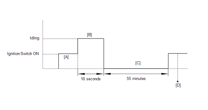
- Connect the Techstream to the DLC3.
- Turn the ignition switch ON and turn the Techstream on.
- Clear the DTCs (even if no DTCs are stored, perform the clear DTC procedure) (See page
 ) [A]. ) [A].
- Start the engine.
- Idle the engine for 10 seconds [B].
- Turn the ignition switch off.
- Soak the vehicle for 55 minutes [C].
- Turn the ignition switch ON and turn the Techstream on.
- Enter the following menus: Powertrain / Engine and ECT / Trouble Codes.
- Read the pending DTCs [D].
- If a pending DTC is output, the system is malfunctioning.
HINT:
If no pending DTC is output, perform the steps below.
- Enter the following menus: Powertrain / Engine and ECT / Utility / All Readiness.
- Input the DTC: P106A or P106B.
- Check the DTC judgment result.
|
Techstream Display |
Description |
|
NORMAL |
- DTC judgment completed
- System normal
|
|
ABNORMAL |
- DTC judgment completed
- System abnormal
|
|
INCOMPLETE |
- DTC judgment not completed
- Perform driving pattern after confirming DTC enabling conditions
|
|
N/A |
- Unable to perform DTC judgment
- Number of DTCs which do not fulfill DTC preconditions has reached ECU's memory limit
|
HINT:
- If the judgment result shows ABNORMAL, the system has a malfunction.
- If the judgment result shows INCOMPLETE or N/A, perform steps [A] through [D] again.
- If no pending DTC is output, perform a universal trip and check for permanent DTCs (See page
).
HINT:
- If a permanent DTC is output, the system is malfunctioning.
- If no permanent DTC is output, the system is normal.
CAUTION / NOTICE / HINT HINT: Read
freeze frame data using the Techstream. The ECM records vehicle and
driving condition information as freeze frame data the moment a DTC is
stored. When troubleshooting, freeze frame data can be helpful in
determining whether the vehicle was moving or stationary, whether the
engine was warmed up or not, whether the air-fuel ratio was lean or
rich, as well as other data recorded at the time of a malfunction. PROCEDURE
| 1. |
CHECK ANY OTHER DTCS OUTPUT (IN ADDITION TO P106A, P106B) |
(a) Connect the Techstream to the DLC3. (b) Turn the ignition switch to ON.
(c) Turn the Techstream on. (d) Enter the following menus: Powertrain / Engine and ECT / Trouble Codes.
(e) Read the DTCs. Result |
Result | Proceed to | |
P106A is output | A | |
P106B is output | B | |
P106A and P106B are output |
C | | P106A, P106B and other DTCs are output |
D | HINT: If any DTCs other than P106A or P106B are output, perform troubleshooting for those DTCs first.
| B |
 | GO TO STEP 3 |
| C |
| GO TO STEP 6 |
| D |
| GO TO DTC CHART |
|
A |
 | |
| 2. |
REPLACE MANIFOLD ABSOLUTE PRESSURE SENSOR |
(a) Replace the manifold absolute pressure sensor (See page
).
| NEXT | |
GO TO STEP 7 |
| 3. |
READ VALUE USING TECHSTREAM (AIR PUMP PRESSURE (ABSOLUTE) AND AIR PUMP2 PRESSURE (ABSOLUTE)) |
(a) Connect the Techstream to the DLC3. (b) Turn the ignition switch to ON.
(c) Turn the Techstream on. (d)
Enter the following menus: Powertrain / Engine and ECT / Data List /
Air Pump Pressure (Absolute), Air Pump2 Pressure (Absolute) and Vapor
Pressure Pump. (e) Read the value. Result |
Result | Proceed to | |
Difference between Air Pump Pressure (Absolute) and Vapor Pressure Pump is more than 3.5 kPa (26 mmHg) |
A | | Difference between Air Pump2 Pressure (Absolute) and Vapor Pressure Pump is more than 3.5 kPa (26 mmHg) |
B |
| B |
| GO TO STEP 5 |
|
A | |
| |
| 4. |
REPLACE AIR SWITCHING VALVE (FOR BANK 1) |
(a) Replace the air switching valve for bank 1 (See page
).
| NEXT | |
GO TO STEP 7 |
| 5. |
REPLACE AIR SWITCHING VALVE (FOR BANK 2) |
(a) Replace the air switching valve for bank 2 (See page
).
| NEXT | |
GO TO STEP 7 |
| 6. |
REPLACE CANISTER PUMP MODULE | (a) Replace the canister pump module (See page
).
NOTICE:
- When replacing the canister pump module, check the canister pump module
interior, canister interior and related pipes for water, fuel and other
liquids. If liquids are present, check for disconnections and/or cracks
in the following: 1) the pipe from the air inlet port to the canister
pump module; 2) the canister filter; and 3) the fuel tank vent hose. If
liquids are present in the canister interior, replace the canister and
canister pump module together.
- Check for filter blockage in the canister. If the charcoal filter inside
the canister is clogged, replace the canister and canister pump module
together.
- Check for filter blockage in the canister filter. If the canister filter
has blockages, replace the fuel tank inlet pipe sub-assembly.
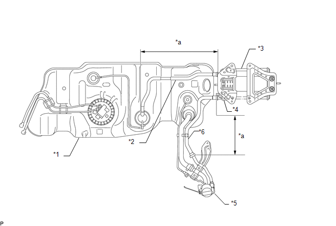 Text in Illustration Text in Illustration |
*1 | Fuel Tank |
*2 | Fuel Tank Vent Hose | |
*3 | Canister Assembly |
*4 | Canister Pump Module - Canister Pressure Sensor
- Leak Detection Pump - Vent Valve | |
*5 | Fuel Tank Inlet Pipe Sub-assembly (Canister Filter) |
*6 | Canister Outlet Hose | |
*a | Inspection Area (check for disconnection and/or cracks) |
- | - |
|
NEXT | |
| |
| 7. |
CONFIRM WHETHER MALFUNCTION HAS BEEN SUCCESSFULLY REPAIRED |
(a) Connect the Techstream to the DLC3. (b) Turn the ignition switch to ON and turn the Techstream on.
(c) Clear the DTCs (See page ). (d) Enter the following menus: Powertrain / Engine and ECT / Data List.
(e)
Compare the Data List items Air Pump Pressure (Absolute) and Vapor
Pressure Pump, Air Pump2 Pressure (Absolute) and Vapor Pressure Pump,
and Vapor Pressure Pump and MAP. (f) Confirm that
the difference between Vapor Pressure Pump and MAP, and between Vapor
Pressure Pump, Air Pump Pressure (Absolute) and Air Pump2 Pressure
(Absolute) is 3.5 kPa (26 mmHg) or less.
| NEXT |
| END | |


