DESCRIPTION By a built-in sensor unit, the manifold absolute pressure sensor detects the intake manifold pressure as a voltage.
 |
DTC No. | DTC Detection Condition |
Trouble Area | | P0107 |
The manifold absolute pressure sensor voltage is below 0.5 V for 0.5 seconds.
(1 trip detection logic) |
- Open or short in manifold absolute pressure sensor circuit
- Manifold absolute pressure sensor
- ECM
| | P0108 |
The manifold absolute pressure sensor voltage is higher than 4.5 V for 0.5 seconds.
(1 trip detection logic) |
- Open or short in manifold absolute pressure sensor circuit
- Manifold absolute pressure sensor
- ECM
| HINT: When
any of these DTCs are output, check the manifold absolute pressure
using the Techstream. Enter the following menus: Powertrain / Engine and
ECT / Data List / MAP. |
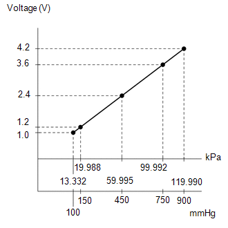
MAP | Malfunction | |
Approximately 0 kPa |
- Short in PIM circuit to ground
- Open in VC circuit
| | 130 kPa or higher |
- Short in VC circuit to PIM circuit
- Open in PIM circuit
- Open in E2 circuit
| MONITOR DESCRIPTION
The
ECM monitors the sensor voltage and uses this value to calculate the
manifold absolute pressure. When the sensor output voltage deviates from
the normal operating range, the ECM interprets this as a malfunction in
the manifold pressure sensor and sets a DTC. Example: When the sensor output voltage remains less than 0.5 V, or more than 4.5 V for more than 0.5 seconds, the ECM sets a DTC.
If the malfunction is not repaired successfully, a DTC is set 0.5 seconds after the engine is next started. MONITOR STRATEGY |
Related DTCs | P0107: Manifold Absolute Pressure (MAP) sensor range check (Low voltage)
P0108: Manifold Absolute Pressure (MAP) sensor range check (High voltage) | |
Required Sensors/Components (Main) | Manifold absolute pressure sensor | |
Required Sensors/Components (Related) |
- | | Frequency of Operation |
Continuous | | Duration |
0.5 seconds | | MIL Operation |
Immediate | | Sequence of Operation |
None | TYPICAL ENABLING CONDITIONS |
Monitor runs whenever following DTCs not present |
None | | Starter |
Off | | Battery voltage |
8 V or more | | Ignition switch |
ON | | Time after starter ON to OFF |
2 seconds or more | TYPICAL MALFUNCTION THRESHOLDS P0107 |
MAP sensor voltage | Below 0.5 V | P0108 |
MAP sensor voltage | Higher than 4.5 V | CONFIRMATION DRIVING PATTERN
- Connect the Techstream to the DLC3.
- Turn the ignition switch to ON and turn the Techstream on.
- Clear DTCs (even if no DTCs are stored, perform the clear DTC operation).
- Turn the ignition switch off and wait for at least 30 seconds.
- Turn the ignition switch to ON and turn the Techstream on.
- Start the engine.
- Idle the engine for 5 seconds [A].
- Enter the following menus: Powertrain / Engine and ECT / Trouble Codes [B].
- Read the pending DTCs.
HINT:
- If a pending DTC is output, the system is malfunctioning.
- If a pending DTC is not output, perform the following procedure.
- Enter the following menus: Powertrain / Engine and ECT / Utility / All Readiness.
- Input the DTC: P0107 or P0108.
- Check the DTC judgment result.
|
Tester Display |
Description |
|
NORMAL |
- DTC judgment completed
- System normal
|
|
ABNORMAL |
- DTC judgment completed
- System abnormal
|
|
INCOMPLETE |
- DTC judgment not completed
- Perform driving pattern after confirming DTC enabling conditions
|
|
N/A |
- Unable to perform DTC judgment
- Number of DTCs which do not fulfill DTC preconditions has reached ECU memory limit
|
HINT:
If the judgment result shows INCOMPLETE or N/A, perform steps [A] through [B] again.
- If no pending DTC is output, perform a universal trip and check for permanent DTCs (See page
 ). ).
HINT:
- If a permanent DTC is output, the system is malfunctioning.
- If no permanent DTC is output, the system is normal.
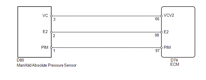
WIRING DIAGRAM
 CAUTION / NOTICE / HINT
HINT:
- If DTCs relating to different systems are stored and they share terminal E2 as their ground, check this ground circuit first.
- Read freeze frame data using the Techstream. The ECM records vehicle and
driving condition information as freeze frame data the moment a DTC is
stored. When troubleshooting, freeze frame data can help determine if
the vehicle was moving or stationary, if the engine was warmed up or
not, if the air fuel ratio was lean or rich, and other data from the
time the malfunction occurred.
PROCEDURE |
1. | READ VALUE USING TECHSTREAM (MANIFOLD ABSOLUTE PRESSURE) |
(a) Connect the Techstream to the DLC3. (b) Turn the ignition switch to ON.
(c) Turn the Techstream on. (d) Enter the following menus: Powertrain / Engine and ECT / Data List / MAP.
(e) Read the MAP value. OK: Same value as the actual atmospheric pressure.
HINT:
- Standard atmospheric pressure is 101 kPa. For every 100 m increase in
altitude, pressure drops by 1 kPa. Varies by weather (high atmospheric
pressure, low atmospheric pressure).
- Also, check "Atmosphere Pressure" in the Data List.
| OK |
 | CHECK FOR INTERMITTENT PROBLEMS |
|
NG |
 | |
| 2. |
CHECK MANIFOLD ABSOLUTE PRESSURE SENSOR (TERMINAL VOLTAGE) |
| (a) Disconnect the manifold absolute pressure sensor connector. |
|
(b) Turn the ignition switch to ON. (c) Measure the voltage according to the value(s) in the table below.
Standard Voltage: |
Tester Connection | Switch Condition |
Specified Condition | |
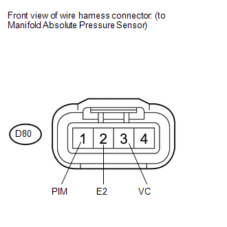
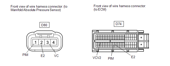
D80-3 (VC) - D80-2 (E2) |
Ignition switch ON | 4.5 to 5.5 V | |
D80-1 (PIM) - D80-2 (E2) |
Ignition switch ON | 3.0 to 5.0 V |
| NG |
| GO TO STEP 5 |
|
OK | |
| |
| 3. |
REPLACE MANIFOLD ABSOLUTE PRESSURE SENSOR |
(a) Replace the manifold absolute pressure sensor (See page
).
|
NEXT | |
| |
| 4. |
CHECK WHETHER DTC OUTPUT RECURS | (a) Connect the Techstream to the DLC3.
(b) Turn the ignition switch to ON and turn the Techstream on. (c) Clear the DTCs (See page
). (d) Turn the ignition switch off and wait for at least 30 seconds.
(e) Turn the ignition switch to ON and wait for 2 seconds. (f) Turn the Techstream on.
(g) Enter the following menus: Powertrain / Engine and ECT / DTC. (h) Read the DTCs. Result |
Display (DTC output) | Proceed to | |
No DTC output | A | |
DTC P0107 and/or P0108 output |
B |
| A |
| END |
| B |
| REPLACE ECM |
| 5. |
CHECK HARNESS AND CONNECTOR (MANIFOLD ABSOLUTE PRESSURE SENSOR - ECM) |
(a) Disconnect the manifold absolute pressure sensor connector.
 (b) Disconnect the ECM connector.
(c) Measure the resistance according to the value(s) in the table below.
Standard Resistance (Check for open): |
Tester Connection | Condition |
Specified Condition | |
D80-1 (PIM) - D74-97 (PIM) |
Always | Below 1 Ω | |
D80-3 (VC) - D74-66 (VCV2) |
Always | Below 1 Ω | |
D80-2 (E2) - D74-98 (E2) |
Always | Below 1 Ω |
Standard Resistance (Check for short): |
Tester Connection | Condition |
Specified Condition | |
D80-1 (PIM) or D74-97 (PIM) - Body ground |
Always | 10 kΩ or higher | |
D80-3 (VC) or D74-66 (VCV2) - Body ground |
Always | 10 kΩ or higher |
| OK |
| REPLACE ECM |
| NG |
| REPAIR OR REPLACE HARNESS OR CONNECTOR | |