Toyota Tundra Service Manual: Thermostat (P0128)

DESCRIPTION

This DTC is stored when the Engine Coolant Temperature (ECT) does not reach 75°C (167°F) despite sufficient engine warm-up time having elapsed.

DTC No.

DTC Detection Condition

Trouble Area

P0128

  • Conditions (a), (b) and (c) met for 5 seconds (2 trip detection logic):
  • (a) Cold start
  • (b) Engine warmed up
  • (c) ECT less than 75°C (167°F)
  • Water inlet with thermostat sub-assembly
  • Cooling system
  • ECT sensor
  • ECM

MONITOR DESCRIPTION

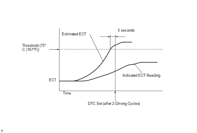
The ECM estimates the ECT based on the starting temperature, engine loads, and engine speeds. The ECM then compares the estimated temperature with the actual ECT. When the estimated ECT reaches 75°C (167°F), the ECM checks the actual ECT. If the actual ECT is less than 75°C (167°F), the ECM interprets this as a malfunction in the thermostat or the engine cooling system and stores the DTC.

MONITOR STRATEGY

Related DTCs

P0128: Coolant Thermostat

Required Sensors/Components (Main)

Thermostat

Required Sensors/Components (Related)

Engine Coolant Temperature (ECT) sensor, Intake Air Temperature (IAT) sensor, Vehicle speed sensor

Frequency of Operation

Once per driving cycle

Duration

920 seconds

MIL Operation

2 driving cycles

Sequence of Operation

None

TYPICAL ENABLING CONDITIONS

Monitor runs whenever following DTCs not present

P0010, P0020 (VVT oil control valve)

P0011, P0021 (VVT system - Advance)

P0012, P0022 (VVT system - Retard)

P0013, P0023 (Exhaust VVT oil control valve)

P0014, P0024 (Exhaust VVT system - Advance)

P0015, P0025 (Exhaust VVT system - Retard)

P0016, P0018 (VVT system - Misalignment)

P0017, P0019 (Exhaust VVT system - Misalignment)

P0031, P0032, P0051, P0052, P101D, P103D (Air fuel ratio sensor heater)

P006A, P0107, P0108 (Manifold absolute pressure)

P0102, P0103 (Mass air flow meter)

P0112, P0113 (Intake air temperature sensor)

P0115, P0117, P0118 (Engine coolant temperature sensor)

P0120, P0121, P0122, P0123, P0220, P0222, P0223, P2135 (Throttle position sensor)

P014C, P014D, P014E, P014F, P015A, P015B, P015C, P015D, P2195, P2196, P2197, P2198, P2237, P2238, P2239, P2240, P2241, P2242, P2252, P2253, P2255, P2256 (Air fuel ratio sensor)

P0171, P0172, P0174, P0175 (Fuel system)

P0301 - P0308 (Misfire)

P0335 (Crankshaft position sensor)

P0340, P0342, P0343, P0345, P0347, P0348 (VVT sensor)

P1340 (Camshaft position sensor)

P0351 - P0358 (Igniter)

P0365, P0367, P0368, P0390, P0392, P0393 (Exhaust VVT sensor)

P0401 (EGR system)

P0500 (Vehicle speed sensor)

P219A, P219B, P219C, P219D, P219E, P219F, P21A0, P21A1, P21A2, P21A3 (Air-fuel ratio imbalance)

Battery voltage

11 V or more

Either of following conditions 1 or 2 met:

-

1. All of following conditions met:

-

  • ECT at engine start - IAT at engine start

-15 to 7°C (-5 to 44.6°F)

  • ECT at engine start

-10 to 56°C (14 to 133°F)

  • IAT at engine start

-10 to 56°C (14 to 133°F)

2. All of following conditions met:

-

  • ECT at engine start - IAT at engine start

More than 7°C (44.6°F)

  • ECT at engine start

56°C (133°F) or less

  • IAT at engine start

-10°C (14°F) or more

Accumulated time at vehicle speed of 128 km/h (80 mph) or more

Less than 20 seconds

TYPICAL MALFUNCTION THRESHOLDS

Duration that both of following conditions (a) and (b) met

5 seconds or more

(a) Estimated ECT

75°C (167°F) or more

(b) ECT sensor output

Below 75°C (167°F)

CONFIRMATION DRIVING PATTERN

  1. Stop the engine and allow it to soak.
  2. Connect the Techstream to the DLC3.
  3. Turn the ignition switch to ON and turn the Techstream on [A].
  4. Enter the following menu items: Powertrain / Engine and ECT / Data List / Coolant Temp and Intake Air.
  5. Check that "Coolant Temp" is 56°C (133°F) or less and "Intake Air" is between 0 and 35°C (0 and 95°F).
  6. Set the heater to MAX HOT with fresh air mode selected and turn the A/C off.
  7. Start the engine and drive the vehicle at 80 km/h (50 mph) for 15 minutes [B].

    CAUTION:

    When performing the confirmation driving pattern, obey all speed limits and traffic laws.

    HINT:

    • Data can be captured relatively easily by using the snapshot function in the Data List.
    • Enter the following menu: Data List / Function / Snap-shot configuration / Record time / 5 min.
    • Data capture can be started by using the target point function. For example, setting the target point to an engine speed of 4000 rpm and then racing the engine, etc. to raise the engine speed to a speed of 4000 rpm or more will cause data capture to start.
  8. After "Coolant Temp" stabilizes, check that "Coolant Temp" is 75°C (167°F) or higher [C].

    HINT:

    If "Coolant Temp" is below 75°C (167°F) while driving the vehicle at 80 km/h (50 mph), inspect the cooling system and thermostat.

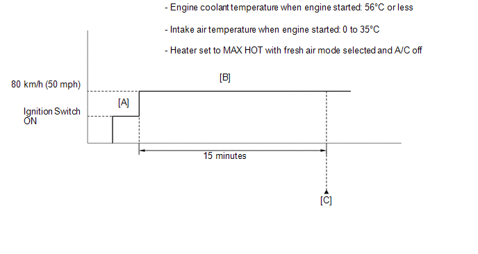
CAUTION / NOTICE / HINT

HINT:

  • When the DTC is output, check the engine coolant temperature using the Techstream. Enter the following menus: Powertrain / Engine and ECT / Data List / Coolant Temp. If the Coolant Temp value is lower than the actual engine coolant temperature, the engine coolant temperature sensor circuit may be malfunctioning. In this case, check the wire harnesses and connectors (and those connections) between the ECM and the engine coolant temperature sensor first.
  • Read freeze frame data using the Techstream. Freeze frame data records the engine condition when malfunctions are detected. When troubleshooting, freeze frame data can help determine if the vehicle was moving or stationary, if the engine was warmed up or not, if the air-fuel ratio was lean or rich, and other data from the time the malfunction occurred.

PROCEDURE

1.

CHECK ANY OTHER DTCS OUTPUT (IN ADDITION TO DTC P0128)

(a) Connect the Techstream to the DLC3.

(b) Turn the ignition switch to ON.

(c) Turn the Techstream on.

(d) Enter the following menus: Powertrain / Engine and ECT / Trouble Codes.

(e) Read DTCs.

Result

Result

Proceed to

P0128 is output

A

P0128 and other DTCs are output

B

HINT:

If any DTCs other than P0128 are output, troubleshoot those DTCs first.

B

GO TO DTC CHART

A

2.

CHECK COOLING SYSTEM

(a) Check for defects in the cooling system that might cause the system to be too cold, such as abnormal radiator fan operation or any modifications.

NG

REPAIR OR REPLACE COOLING SYSTEM

OK

3.

INSPECT WATER INLET WITH THERMOSTAT SUB-ASSEMBLY

(a) Remove the water inlet with thermostat sub-assembly (See page ).

(b) Measure the valve opening temperature of the thermostat.

Standard opening temperature:

80 to 84°C (176 to 183°F)

HINT:

In addition to the above check, confirm that the valve is completely closed when the temperature is below the standard.

NG

REPLACE WATER INLET WITH THERMOSTAT SUB-ASSEMBLY

OK

4.

INSPECT ENGINE COOLANT TEMPERATURE SENSOR

(a) Inspect the engine coolant temperature sensor (See page ).

OK

REPLACE ECM

NG

REPLACE ENGINE COOLANT TEMPERATURE SENSOR

    Insufficient Coolant Temperature for Closed Loop Fuel Control (P0125)

    Oxygen Sensor Circuit (Bank 1 Sensor 2) (P0136-P0139,P013A,P013C,P0156-P0159)

    See More:

    Toyota Tundra Service Manual > Tire And Wheel: Tire Pressure Warning Receiver
    ComponentsCOMPONENTS ILLUSTRATION *A for CrewMax - - *1 TIRE PRESSURE WARNING ECU AND RECEIVER *2 CONNECTOR N*m (kgf*cm, ft.*lbf): Specified torque - - ILLUSTRATION *A for Double Cab - - *1 TIRE PRESSURE WARNING ECU AND RECEIVER *2 CONNECTOR N*m (kgf*cm, ft.*lbf): Specified torque - - InstallationI ...

    Toyota Tundra Owners Manual

    Toyota Tundra Service Manual

    © 2024 Copyright www.ttundra.com
    0.0275