DESCRIPTION A flat type knock sensor (non-resonant type) has a structure that can detect vibrations between approximately 5 kHz and 15 kHz.
Knock sensors are fitted onto the engine block to detect engine knocking.
The knock sensor contains a piezoelectric element which generates a voltage when it becomes deformed.
The
voltage is generated when the engine block vibrates due to knocking.
Any occurrence of engine knocking can be suppressed by delaying the
ignition timing. |
DTC No. | DTC Detection Condition |
Trouble Area | | P0327 |
Output voltage of knock sensor (for Bank 1 Sensor 1) is 0.5 V or less
(1 trip detection logic) |
- Short in knock sensor (for Bank 1 Sensor 1) circuit
- Knock sensor (for Bank 1 Sensor 1)
- ECM
| | P0328 |
Output voltage of knock sensor (for Bank 1 Sensor 1) is 4.5 V or more
(1 trip detection logic) |
- Open in knock sensor (for Bank 1 Sensor 1) circuit
- Knock sensor (for Bank 1 Sensor 1)
- ECM
| | P0332 |
Output voltage of knock sensor (for Bank 2 Sensor 1) is 0.5 V or less
(1 trip detection logic) |
- Short in knock sensor (for Bank 2 Sensor 1) circuit
- Knock sensor (for Bank 2 Sensor 1)
- ECM
| | P0333 |
Output voltage of knock sensor (for Bank 2 Sensor 1) is 4.5 V or more
(1 trip detection logic) |
- Open in knock sensor (for Bank 2 Sensor 1) circuit
- Knock sensor (for Bank 2 Sensor 1)
- ECM
| | P032C |
Output voltage of knock sensor (for Bank 1 Sensor 2) is 0.5 V or less
(1 trip detection logic) |
- Short in knock sensor (for Bank 1 Sensor 2) circuit
- Knock sensor (for Bank 1 Sensor 2)
- ECM
| | P032D |
Output voltage of knock sensor (for Bank 1 Sensor 2) is 4.5 V or more
(1 trip detection logic) |
- Open in knock sensor (for Bank 1 Sensor 2) circuit
- Knock sensor (for Bank 1 Sensor 2)
- ECM
| | P033C |
Output voltage of knock sensor (for Bank 2 Sensor 2) is 0.5 V or less
(1 trip detection logic) |
- Short in knock sensor (for Bank 2 Sensor 2) circuit
- Knock sensor (for Bank 2 Sensor 2)
- ECM
| | P033D |
Output voltage of knock sensor (for Bank 2 Sensor 2) is 4.5 V or more
(1 trip detection logic) |
- Open in knock sensor (for Bank 2 Sensor 2) circuit
- Knock sensor (for Bank 2 Sensor 2)
- ECM
| HINT: When
DTC P0327, P0328, P0332, P0333, P032C, P032D, P033C or P033D is stored,
the ECM enters fail-safe mode. During fail-safe mode, the ignition
timing is delayed to its maximum retardation. Fail-safe mode continues
until the ignition switch is turned off. Reference: Inspection using an oscilloscope
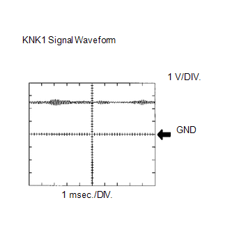 Standard: |
Tester Connection | Tool Setting |
Condition | Specified Condition | |
D74-94 (KNK1) - D74-93 (EKNK) |
0.01 to 10 V/DIV. 0.01 to 10 msec./DIV. |
Keep engine speed at 4000 rpm with warm engine |
The correct waveform is as shown | |
D74-117 (KNK2) - D74-116 (EKN2) |
0.01 to 10 V/DIV. 0.01 to 10 msec./DIV. |
Keep engine speed at 4000 rpm with warm engine |
The correct waveform is as shown | |
D74-96 (KNK3) - D74-95 (EKN3) |
0.01 to 10 V/DIV. 0.01 to 10 msec./DIV. |
Keep engine speed at 4000 rpm with warm engine |
The correct waveform is as shown | |
D74-119 (KNK4) - D74-118 (EKN4) |
0.01 to 10 V/DIV. 0.01 to 10 msec./DIV. |
Keep engine speed at 4000 rpm with warm engine |
The correct waveform is as shown | MONITOR DESCRIPTION
The
knock sensor, located on the cylinder block, detects spark knock. When
spark knock occurs, the piezoelectric element of the sensor vibrates.
When the ECM detects a voltage in this frequency range, it retards the
ignition timing to suppress the spark knock. The
ECM also senses background engine noise with the knock sensor and uses
this noise to check for faults in the sensor. If the knock sensor signal
level is too low for more than 10 seconds, or if the knock sensor
output voltage is outside the normal range, the ECM interprets this as a
fault in the knock sensor and stores a DTC. MONITOR STRATEGY |
Related DTCs | P0327: Knock sensor (for Bank 1 Sensor 1) open/short (Low voltage)
P0328: Knock sensor (for Bank 1 Sensor 1) open/short (High voltage)
P0332: Knock sensor (for Bank 2 Sensor 1) open/short (Low voltage)
P0333: Knock sensor (for Bank 2 Sensor 1) open/short (High voltage)
P032C: Knock sensor (for Bank 1 Sensor 2) open/short (Low voltage)
P032D: Knock sensor (for Bank 1 Sensor 2) open/short (High voltage)
P033C: Knock sensor (for Bank 2 Sensor 2) open/short (Low voltage)
P033D: Knock sensor (for Bank 2 Sensor 2) open/short (High voltage) | |
Required Sensors/Components (Main) | Knock sensor (Bank 1, 2 Sensor 1, 2) | |
Required Sensors/Components (Related) |
- | | Frequency of Operation |
Continuous | | Duration |
1 second | | MIL Operation |
Immediate | | Sequence of Operation |
None | TYPICAL ENABLING CONDITIONS |
Monitor runs whenever following DTCs are not present |
None | | Battery voltage |
10.5 V or more | | Time after engine start |
5 seconds or more | TYPICAL MALFUNCTION THRESHOLDS Knock Sensor Range Check (Low Voltage): P0327, P0332, P032C and P033C |
Knock sensor voltage | Below 0.5 V | Knock Sensor Range Check (High Voltage): P0328, P0333, P032D and P033D |
Knock sensor voltage | Higher than 4.5 V | CONFIRMATION DRIVING PATTERN
- Connect the Techstream to the DLC3.
- Turn the ignition switch to ON and turn the Techstream on.
- Clear DTCs (even if no DTCs are stored, perform the clear DTC operation).
- Turn the ignition switch off and wait for at least 30 seconds.
- Turn the ignition switch to ON and turn the Techstream on.
- Start the engine and wait 10 seconds.
- Enter the following menus: Powertrain / Engine and ECT / Trouble Codes.
- Read the pending DTCs.
HINT:
- If a pending DTC is output, the system is malfunctioning.
- If a pending DTC is not output, perform the following procedure.
- Enter the following menus: Powertrain / Engine and ECT / Utility / All Readiness.
- Input the DTC: P0327, P0328, P032C, P032D, P0332, P0333, P033C or P033D.
- Check the DTC judgment result.
|
Tester Display |
Description |
|
NORMAL |
- DTC judgment completed
- System normal
|
|
ABNORMAL |
- DTC judgment completed
- System abnormal
|
|
INCOMPLETE |
- DTC judgment not completed
- Perform driving pattern after confirming DTC enabling conditions
|
|
N/A |
- Unable to perform DTC judgment
- Number of DTCs which do not fulfill DTC preconditions has reached ECU memory limit
|
HINT:
- If the judgment result shows NORMAL, the system is normal.
- If the judgment result shows ABNORMAL, the system has a malfunction.
- If the judgment result shows INCOMPLETE or N/A, idle the engine for 5 minutes and check the DTC judgment result again.
- If no pending DTC is output, perform a universal trip and check for permanent DTCs (See page
 ). ).
HINT:
- If a permanent DTC is output, the system is malfunctioning.
- If no permanent DTC is output, the system is normal.
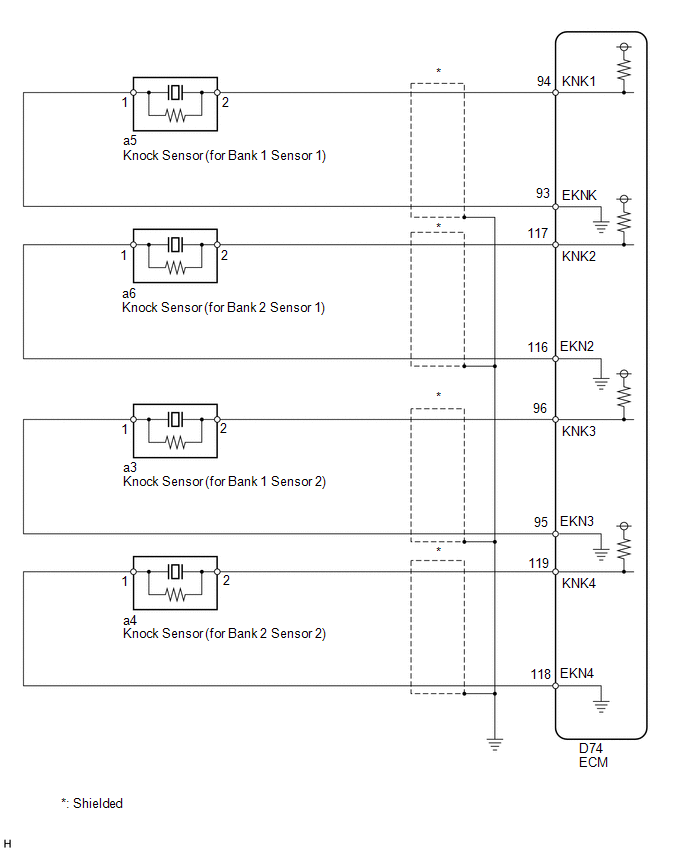
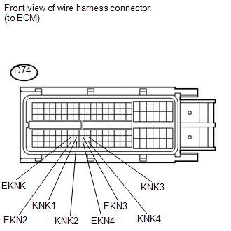
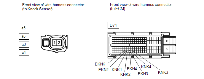
WIRING DIAGRAM
 CAUTION / NOTICE / HINT
HINT:
PROCEDURE
 (a) Disconnect the ECM connector.
(b) Measure the resistance according to the value(s) in the table below.
Standard Resistance: |
Tester Connection | Condition |
Specified Condition | |
D74-94 (KNK1) - D74-93 (EKNK) |
20°C (68°F) | 120 to 280 kΩ | |
D74-117 (KNK2) - D74-116 (EKN2) |
20°C (68°F) | 120 to 280 kΩ | |
D74-96 (KNK3) - D74-95 (EKN3) |
20°C (68°F) | 120 to 280 kΩ | |
D74-119 (KNK4) - D74-118 (EKN4) |
20°C (68°F) | 120 to 280 kΩ | Result |
Result | Proceed to | |
NG | A | |
OK | B |
| B |
 | GO TO STEP 3 |
|
A |
 | |
| 2. |
CHECK HARNESS AND CONNECTOR (ECM - KNOCK SENSOR) |
 (a) Disconnect the ECM connector.
(b) Disconnect the knock sensor connector. (c) Measure the resistance according to the value(s) in the table below.
Standard Resistance: |
Tester Connection | Condition |
Specified Condition | |
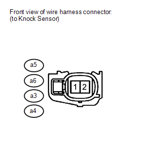
a5-2 - D74-94 (KNK1) |
Always | Below 1 Ω | |
a5-1 - D74-93 (EKNK) |
Always | Below 1 Ω | |
a6-2 - D74-117 (KNK2) |
Always | Below 1 Ω | |
a6-1 - D74-116 (EKN2) |
Always | Below 1 Ω | |
a3-2 - D74-96 (KNK3) |
Always | Below 1 Ω | |
a3-1 - D74-95 (EKN3) |
Always | Below 1 Ω | |
a4-2 - D74-119 (KNK4) |
Always | Below 1 Ω | |
a4-1 - D74-118 (EKN4) |
Always | Below 1 Ω | |
a5-2 or D74-94 (KNK1) - Body ground |
Always | 10 kΩ or higher | |
a5-1 or D74-93 (EKNK) - Body ground |
Always | 10 kΩ or higher | |
a6-2 or D74-117 (KNK2) - Body ground |
Always | 10 kΩ or higher | |
a6-1 or D74-116 (EKN2) - Body ground |
Always | 10 kΩ or higher | |
a3-2 or D74-96 (KNK3) - Body ground |
Always | 10 kΩ or higher | |
a3-1 or D74-95 (EKN3) - Body ground |
Always | 10 kΩ or higher | |
a4-2 or D74-119 (KNK4) - Body ground |
Always | 10 kΩ or higher | |
a4-1 or D74-118 (EKN4) - Body ground |
Always | 10 kΩ or higher |
HINT: Perform "Inspection After Repair" after replacing the knock sensor (See page
).
| OK | |
REPLACE KNOCK SENSOR |
| NG |
| REPAIR OR REPLACE HARNESS OR CONNECTOR |
(a) Disconnect the knock sensor connector.
| (b) Turn the ignition switch to ON. | |
(c) Measure the voltage according to the value(s) in the table below. Standard Voltage: |
Tester Connection | Switch Condition |
Specified Condition | |
a5-1 - a5-2 | Ignition switch ON |
4.5 to 5.5 V | |
a6-1 - a6-2 | Ignition switch ON |
4.5 to 5.5 V | |
a3-1 - a3-2 | Ignition switch ON |
4.5 to 5.5 V | |
a4-1 - a4-2 | Ignition switch ON |
4.5 to 5.5 V |
| OK |
| CHECK FOR INTERMITTENT PROBLEMS |
| NG |
| REPLACE ECM | |