|
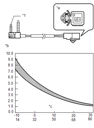
(a) Measure the resistance according to the value(s) in the table below.
Standard Resistance:
|
Tester Connection
|
Condition
|
Specified Condition
|
|
1 - 2
|
-10°C (14°F)
|
7.30 to 9.10 kΩ
|
|
-5°C (23°F)
|
5.65 to 6.95 kΩ
|
|
0°C (32°F)
|
4.40 to 5.35 kΩ
|
|
5°C (41°F)
|
3.40 to 4.15 kΩ
|
|
10°C (50°F)
|
2.70 to 3.25 kΩ
|
|
15°C (59°F)
|
2.14 to 2.58 kΩ
|
|
20°C (68°F)
|
1.71 to 2.05 kΩ
|
|
25°C (77°F)
|
1.38 to 1.64 kΩ
|
|
30°C (86°F)
|
1.11 to 1.32 kΩ
|
NOTICE:
- Even slightly touching the sensor may change the resistance value.
Be sure to hold the connector of the sensor.
- When measuring, the sensor temperature must be almost the same as
the ambient temperature.
HINT:
As the temperature increases, the resistance decreases (see the graph).
Text in Illustration
|
*1
|
Sensor
|
|
*a
|
Component without harness connected
(No. 1 Cooler Thermistor)
|
|
*b
|
Resistance (kΩ)
|
|
*c
|
Temperature (°C (°F))
|
If the result is not as specified, replace the sensor.
|
|