DESCRIPTION Based on the
driving conditions, the ECM regulates the volume of exhaust gas that is
recirculated to the engine's combustion chambers and thus lowers the
combustion temperature to reduce NOx emissions. The ECM monitors signals
such as engine speed, coolant temperature, electric load, and vehicle
speed. When the EGR permission conditions are fulfilled, the ECM
controls the opening of the EGR valve linearly through signals to the
EGR stepper motor. |
DTC No. | DTC Detection Condition |
Trouble Area | | P0401 |
Change in intake manifold pressure is small when the EGR valve is opened and closed during idle fuel cut operation
(2 trip detection logic) |
- EGR valve assembly
- EGR passages
- EGR cooler assembly
- Manifold absolute pressure sensor
- Intake system
| MONITOR DESCRIPTION
The
ECM monitors the pressure inside the intake manifold while opening and
closing the EGR valve during fuel cut operation. If there is no change
in the manifold absolute pressure sensor value, the ECM interprets this
as a malfunction in the EGR valve assembly, illuminates the MIL and
stores the DTC (2 trip detection logic). MONITOR STRATEGY |
Related DTC | P0401: EGR valve high flow rate / low flow rate | |
Required sensors/Components (Main) | EGR valve assembly, manifold absolute pressure sensor | |
Required sensors/Components (Related) |
Engine coolant temperature sensor, vehicle speed sensor | |
Frequency of operation | Once per driving cycle | |
Duration | 3 seconds | |
MIL operation | 2 driving cycles | |
Sequence of operation | None | TYPICAL ENABLING CONDITIONS |
Monitor runs whenever following DTCs are not present |
P0010, P0020 (VVT oil control valve) P0011, P0021 (VVT system - Advance)
P0012, P0022 (VVT system - Retard) P0013, P0023 (Exhaust VVT oil control valve)
P0014, P0024 (Exhaust VVT system - Advance) P0015, P0025 (Exhaust VVT system - Retard)
P0016, P0018 (VVT system - Misalignment) P0017, P0019 (Exhaust VVT system - Misalignment)
P0031, P0032, P0051, P0052, P101D, P103D (Air fuel ratio sensor heater)
P006A, P0107, P0108 (Manifold absolute pressure) P0102, P0103 (Mass air flow meter)
P0112, P0113 (Intake air temperature sensor) P0115, P0117, P0118 (Engine coolant temperature sensor)
P0120, P0121, P0122, P0123, P0220, P0222, P0223, P2135 (Throttle position sensor)
P0125 (Insufficient Coolant Temperature for Closed Loop Fuel Control)
P014C,
P014D, P014E, P014F, P015A, P015B, P015C, P015D, P2195, P2196, P2197,
P2198, P2237, P2238, P2239, P2240, P2241, P2242, P2252, P2253, P2255,
P2256 (Air fuel ratio sensor) P0171, P0172, P0174, P0175 (Fuel system)
P0327, P0328, P032C, P032D, P0332, P0333, P033C, P033D (Knock Sensor)
P0335 (Crankshaft position sensor) P0340, P0342, P0343, P0345, P0347, P0348 (VVT sensor)
P1340 (Camshaft position sensor) P0351 - P0358 (Igniter) P0365, P0367, P0368, P0390, P0392, P0393 (Exhaust VVT sensor)
P0412, P0415, P0418, P0419, P1613, P1614 (Secondary Air Injection System Control)
P0500 (Vehicle speed sensor) P106A (Evaporative Emission System Pressure Sensor)
P219A, P219B, P219C, P219D, P219E, P219F, P21A0, P21A1, P21A2, P21A3 (Air-fuel ratio imbalance)
P2440, P2441, P2442, P2443, P2444, P2445, P2446, P2447 (Secondary Air Injection System) | |
Time after engine started | 3 seconds or more | |
Time after engine fuel cut | 1 second or more | |
Engine speed | 1200 to 1800 rpm | |
Vehicle speed | 20 km/h (12.5 mph) or more | |
Engine speed change (per 65 msec.) | -40 to 10 rpm | |
Time after engine load becomes stable (Brake, lock-up) |
More than 1 sec | | Shift position |
Except "P" or "N" range | | Engine coolant temperature |
75°C (167°F) or more | | Battery voltage |
11 V or more | | Intake air temperature |
-10°C (14°F) or more | | Atmospheric pressure |
76 kPa (570 mmHg) or more | TYPICAL MALFUNCTION THRESHOLDS |
Manifold pressure change | Less than 1.8125 kPa (14 mmHg) | |
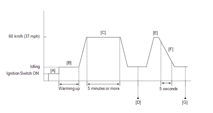
Engine speed | 1400 rpm | CONFIRMATION DRIVING PATTERN
- Connect the Techstream to the DLC3.
- Turn the ignition switch ON and turn the Techstream on.
- Clear the DTCs (even if no DTCs are stored, perform the clear DTC procedure) (See page
 ). ).
- Turn the ignition switch off and wait for 30 seconds.
- Turn the ignition switch ON and turn the Techstream on [A].
- Start the engine and warm it up until the engine coolant temperature reaches 75°C (167°F) or more [B].
HINT:
The A/C switch and all accessory switches should be off and the shift lever should be in P or N.
- Drive the vehicle at 60 km/h (37 mph) for 5 minutes or more [C].
CAUTION:
When performing the confirmation driving pattern, obey all speed limits and traffic laws.
- Idle the engine for 30 seconds or more [D].
- Drive the vehicle at 60 km/h (37 mph) and select the S4 range with the shift lever in S [E].
CAUTION:
When performing the confirmation driving pattern, obey all speed limits and traffic laws.
- Perform fuel cut operation for 5 seconds or more with the accelerator pedal fully released [F].
HINT:
When "Idle Fuel Cut" in the Data List is ON, fuel cut is operating.
- Enter the following menus: Powertrain / Engine and ECT / Monitor /
Current Monitor / Exhaust Gas Recirculation/VVT / Current [G].
- Check that the Exhaust Gas Recirculation/VVT / Current monitor is Complete.
HINT:
If the monitor is Incomplete, perform the driving pattern again.
- Enter the following menus: Powertrain / Engine and ECT / Monitor /
Current Monitor / Exhaust Gas Recirculation/VVT / Details / EGR FLOW
INSUFFICIENCY / Details.
- Check the test Details (EGR FLOW INSUFFICIENCY).
HINT:
Make sure that the values are between MIN and MAX.
- If the monitor is still Incomplete, perform the following procedure.
- Enter the following menus: Powertrain / Engine and ECT / Trouble Codes.
- Read the pending DTCs.
HINT:
- If a pending DTC is output, the system is malfunctioning.
- If a pending DTC is not output, perform the following procedure.
- Enter the following menus: Powertrain / Engine and ECT / Utility / All Readiness.
- Input the DTC: P0401.
- Check the DTC judgment result.
|
Techstream Display |
Description |
|
NORMAL |
- DTC judgment completed
- System normal
|
|
ABNORMAL |
- DTC judgment completed
- System abnormal
|
|
INCOMPLETE |
- DTC judgment not completed
- Perform driving pattern after confirming DTC enabling conditions
|
|
N/A |
- Unable to perform DTC judgment
- Number of DTCs which do not fulfill DTC preconditions has reached ECU's memory limit
|
HINT:
- If the judgment result shows ABNORMAL, the system has a malfunction.
- If the DTC judgment result is INCOMPLETE or N/A and no pending DTC is
output, drive the vehicle again at 60 km/h (37 mph) and select the S4
range with the shift lever in S, perform fuel cut operation for 5
seconds or more with the accelerator pedal fully released, and then
check the DTC judgment result.
- If the test result is INCOMPLETE or N/A and no pending DTC is output,
perform a universal trip and check for permanent DTCs (See page
).
HINT:
- If a permanent DTC is output, the system is malfunctioning.
- If no permanent DTC is output, the system is normal.
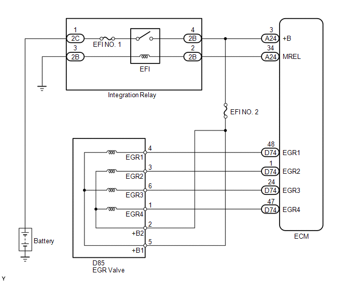
WIRING DIAGRAM
 CAUTION / NOTICE / HINT
HINT:
- By using the Control the EGR Step Position Active Test, the operation of the EGR valve can be checked.
- When the engine is idling steadily with the EGR valve fully closed, if
the EGR valve is normal and it is opened using the Active Test, the Data
List values will change as follows.
|
Data List |
Change in Data List when Number of Steps is Increased Using Control the EGR Step Position Active Test
|
|
Engine Speed |
Idle becomes rough |
|
MAP |
Pressure rises |
- Read freeze frame data using the Techstream. The ECM records vehicle and
driving condition information as freeze frame data the moment a DTC is
stored. When troubleshooting, freeze frame data can help determine if
the vehicle was moving or stationary, if the engine was warmed up or
not, if the air fuel ratio was lean or rich, and other data from the
time the malfunction occurred.
PROCEDURE |
1. | CHECK ANY OTHER DTCS OUTPUT (IN ADDITION TO P0401) |
(a) Connect the Techstream to the DLC3. (b) Turn the ignition switch to ON.
(c) Turn the Techstream on. (d) Enter the following menus: Powertrain / Engine and ECT / Trouble Codes.
(e) Read the DTCs. Result |
Result | Proceed to | |
DTC P0401 is output | A | |
DTC P0401 and other DTCs are output |
B | HINT: If any DTCs other than P0401 are output, perform troubleshooting for those DTCs first.
| B |
 | GO TO DTC CHART |
|
A |
 | |
| 2. |
PERFORM ACTIVE TEST USING TECHSTREAM (OPERATE EGR VALVE) |
(a) Connect the Techstream to the DLC3. (b) Start the engine and warm it up until the engine coolant temperature reaches 75°C (167°F) or higher.
HINT:
- When performing the Active Test, make sure the shift lever is in P or N.
- The A/C switch and all accessory switches should be off.
(c) Turn the Techstream on. (d) Enter the following menus: Powertrain / Engine and ECT / Active Test / Control the EGR Step Position.
(e)
Confirm the Throttle Idle Position is ON and check the engine idling
condition and MAP values in the Data List while performing the Active
Test.
HINT:
- Do not leave the EGR valve open for 10 seconds or more during the Active Test.
- Be sure to return the EGR valve to step 0 when the Active Test is completed.
OK: MAP and idling condition change in response to EGR step position as follows.
Standard: |
- | EGR Step Position (Active Test) | |
0 Steps | 0 to 30 Steps | |
Idling condition | Steady idling |
Idling changes from steady to rough idling or engine stall | |
MAP (Data List) |
- | MAP value is at least +10 kPa (75 mmHg) higher than when EGR valve is fully closed |
| NG |
| GO TO STEP 4 |
|
OK | |
| |
| 3. |
INSPECT EGR VALVE ASSEMBLY | (a) Confirm that there are no deposits on the EGR valve.
(b) Confirm that the EGR valve is closed. OK: There are no deposits and the valve is closed.
| OK |
| GO TO STEP 5 |
|
NG | |
| |
| 4. |
REPLACE EGR VALVE ASSEMBLY | (a) Replace the EGR valve assembly (See page
). HINT: Perform "Inspection After Repair" after replacing the EGR valve assembly (See page
).
|
NEXT | |
| |
| 5. |
CHECK FOR DEPOSIT (EGR VALVE ASSEMBLY TO INTAKE PORT) |
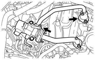 (a) Check for exhaust leaks at each connection point.
(b) Check for cracks, damage and blockage of the pipes between the intake manifold converter and EGR valve assembly.
HINT: This check may require the removal of components. (c) Check for blockage due to deposits in the EGR valve and pipes.
OK: No deposits.
| NG | |
REPAIR OR REPLACE MALFUNCTIONING PARTS |
|
OK | |
| |
| 6. |
CHECK FOR DEPOSIT (EXHAUST MANIFOLD CONVERTER TO EGR VALVE ASSEMBLY) |
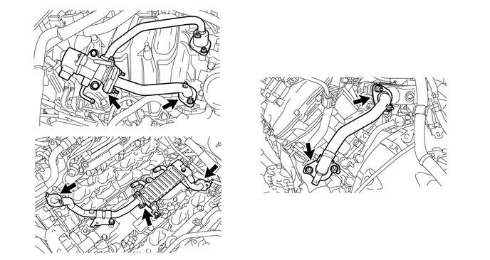 (a) Check for exhaust leaks at each connection point.
(b) Check for cracks, damage and blockage of the pipes between the exhaust manifold converter and EGR valve assembly.
HINT: This check may require the removal of components. (c) Check for blockage due to deposits in the EGR valve and pipes.
OK: No deposits.
| NG | |
REPAIR OR REPLACE MALFUNCTIONING PARTS |
|
OK | |
| |
| 7. |
INSPECT EGR COOLER ASSEMBLY | (a) Check for blockage in the EGR cooler assembly.
| NG |
| REPAIR OR REPLACE EGR COOLER ASSEMBLY |
|
OK | |
| |
| 8. |
READ VALUE USING TECHSTREAM (MANIFOLD ABSOLUTE PRESSURE SENSOR) |
(a) Connect the Techstream to the DLC3. (b) Turn the ignition switch to ON.
(c) Turn the Techstream on. (d) Enter the following menus: Powertrain / Engine and ECT / Data List / MAP.
(e) Read the MAP value. Standard: |
Switch Condition | Techstream Display | |
Ignition switch ON | 80 to 110 kPa (600 to 825 mmHg) |
(f) Read the MAP value when racing the engine. Standard: |
Engine Condition | Techstream Display | |
Idling | 20 to 40 kPa (150 to 300 mmHg) |
| OK |
| GO TO STEP 11 |
|
NG | |
| |
(a) Check the intake system for vacuum leaks (See page
). OK: No leaks in intake system.
HINT: Perform "Inspection After Repair" after repairing or replacing the intake system (See page
).
| NG | |
REPAIR OR REPLACE INTAKE SYSTEM |
|
OK | |
| |
| 10. |
REPLACE MANIFOLD ABSOLUTE PRESSURE SENSOR |
(a) Replace the manifold absolute pressure sensor (See page
).
|
NEXT | |
| |
| 11. |
CONFIRM WHETHER MALFUNCTION HAS BEEN SUCCESSFULLY REPAIRED |
(a) Connect the Techstream to the DLC3. (b) Turn the ignition switch to ON.
(c) Turn the Techstream on. (d) Clear the DTC (See page
). (e) Turn the ignition switch off and wait for 30 seconds.
(f) Turn the ignition switch to ON and turn the Techstream on. (g) Start the engine and warm it up until the engine coolant temperature reaches 75°C (167°F) or more.
HINT: The A/C switch and all accessory switches should be off. (h) Drive the vehicle at 60 km/h (37 mph) for 5 minutes or more.
CAUTION: Strictly observe speed limits and traffic laws when performing the confirmation drive pattern.
(i) Idle the engine for 30 seconds or more. (j) Drive the vehicle at 60 km/h (37 mph).
CAUTION: Strictly observe speed limits and traffic laws when performing the confirmation drive pattern.
(k) Perform fuel cut operation for 5 seconds or more with the accelerator pedal fully released.
HINT: If the deceleration was not completed, perform the Confirmation Driving Pattern again.
(l) Enter the following menus: Powertrain / Engine and ECT / Trouble Codes / Pending.
(m) Read the pending DTCs. (n) If a pending DTC is output, the system is malfunctioning.
HINT: If a pending DTC is not output, perform the following procedure.
(o) Enter the following menus: Powertrain / Engine and ECT / Utility / All Readiness.
(p) Input the DTC: P0401. (q) Check the DTC judgment result. |
Techstream Display | Description | |
NORMAL |
- DTC judgment completed
- System normal
| | ABNORMAL |
- DTC judgment completed
- System abnormal
| | INCOMPLETE |
- DTC judgment not completed
- Perform driving pattern after confirming DTC enabling conditions
| | N/A |
- Unable to perform DTC judgment
- Number of DTCs which do not fulfill DTC preconditions has reached ECU's memory limit
|
| NEXT |
| END | |


