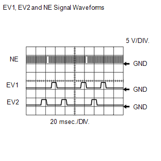
DESCRIPTION The exhaust
camshaft's Variable Valve Timing (VVT) sensor (EV1 and EV2 signal)
consists of a magnet and MRE (Magnetoresistive Element). The
exhaust camshaft has a sensor plate with 3 teeth on its outer
circumference. When the exhaust camshaft rotates, changes occur in the
air gaps between the 3 teeth and MRE, which affects the magnet. As a
result, the resistance of the MRE fluctuates. The VVT sensor converts
the exhaust camshaft rotation data into pulse signals, uses the pulse
signals to determine the camshaft angle, and sends it to the ECM. |
DTC No. | DTC Detection Condition |
Trouble Area | | P0365
P0390 | No VVT sensor signal to ECM at engine speed of 600 rpm or more
(1 trip detection logic) |
- Open or short in VVT sensor (for exhaust side of bank 1, 2) circuit
- VVT sensor (for exhaust side of bank 1, 2)
- Exhaust camshaft
- Timing chain jumped tooth
- ECM
| | P0367
P0392 | Output voltage of VVT sensor less than 0.3 V for 4 seconds
(1 trip detection logic) |
- Open or short in VVT sensor (for exhaust side of bank 1, 2) circuit
- VVT sensor (for exhaust side of bank 1, 2)
- Exhaust camshaft
- Timing chain jumped tooth
- ECM
| | P0368
P0393 | Output voltage of VVT sensor more than 4.7 V for 4 seconds
(1 trip detection logic) |
- Open or short in VVT sensor (for exhaust side of bank 1, 2) circuit
- VVT sensor (for exhaust side of bank 1, 2)
- Exhaust camshaft
- Timing chain jumped tooth
- ECM
|
MONITOR DESCRIPTION If
no signal is transmitted by the VVT sensor despite the camshaft
revolving, or the rotations of the camshaft and the crankshaft are not
synchronized, the ECM interprets this as a malfunction of the sensor. When the sensor output voltage remains at less than 0.3 V, or more than 4.7 V for more than 4 seconds, the ECM stores a DTC. MONITOR STRATEGY |
Related DTCs | P0365: VVT position sensor (for Bank 1) verify pulse input
P0367: VVT position sensor (for Bank 1) range check (low voltage) P0368: VVT position sensor (for Bank 1) range check (high voltage)
P0390: VVT position sensor (for Bank 2) verify pulse input P0392: VVT position sensor (for Bank 2) range check (low voltage)
P0393: VVT position sensor (for Bank 2) range check (high voltage) | |
Required Sensors/Components (Main) | VVT position sensor (for Bank 1 and 2) | |
Required Sensors/Components (Related) |
Crankshaft position sensor | |
Frequency of Operation | Continuous | |
Duration | P0365, P0390: 5 seconds
P0367, P0368, P0392, P0393: 4 seconds | |
MIL Operation | Immediate | |
Sequence of Operation | None | TYPICAL ENABLING CONDITIONS ALL: |
Monitor runs whenever following DTCs are not stored |
None | P0365, P0390 (Verify pulse input): |
Engine speed | 600 rpm or more | |
Battery voltage | 8 V or higher | |
Starter | OFF | | Ignition switch |
ON | | Exhaust VVT sensor voltage |
0.3 to 4.7 V | | Exhaust VVT sensor range check low voltage fail (P0367, P0392) |
Not detected | | Exhaust VVT sensor range check high voltage fail (P0368, P0393) |
Not detected | P0367, P0368, P0392, P0393 (Low voltage, High voltage): |
Starter | OFF | | Ignition switch |
ON | | Time after ignition switch off to ON |
2 seconds or more | | Exhaust VVT sensor verify pulse input fail (P0365, P0390) |
Not detected | | Battery voltage |
8 V or higher | TYPICAL MALFUNCTION THRESHOLDS P0365, P0390 |
Exhaust VVT sensor signal | No signal | P0367, P0392 |
Exhaust VVT sensor voltage | Below 0.3 V | P0368, P0393 |
Exhaust VVT sensor voltage | Higher than 4.7 V | COMPONENT OPERATING RANGE |
VVT sensor voltage | 0.3 to 4.7 V | CONFIRMATION DRIVING PATTERN
- Connect the Techstream to the DLC3.
- Turn the ignition switch to ON and turn the Techstream on.
- Clear DTCs (even if no DTCs are stored, perform the clear DTC operation).
- Turn the ignition switch off and wait for at least 30 seconds.
- Turn the ignition switch to ON and turn the Techstream on.
- Start the engine.
- Idle the engine for 10 seconds or more [A].
- Enter the following menus: Powertrain / Engine and ECT / Trouble Codes [B].
- Read the pending DTCs.
HINT:
- If a pending DTC is output, the system is malfunctioning.
- If a pending DTC is not output, perform the following procedure.
- Enter the following menus: Powertrain / Engine and ECT / Utility / All Readiness.
- Input the DTC: P0365, P0367, P0368, P0390, P0392 or P0393.
- Check the DTC judgment result.
|
Tester Display |
Description |
|
NORMAL |
- DTC judgment completed
- System normal
|
|
ABNORMAL |
- DTC judgment completed
- System abnormal
|
|
INCOMPLETE |
- DTC judgment not completed
- Perform driving pattern after confirming DTC enabling conditions
|
|
N/A |
- Unable to perform DTC judgment
- Number of DTCs which do not fulfill DTC preconditions has reached ECU memory limit
|
HINT:
- If the judgment result shows ABNORMAL, the system has a malfunction.
- If the judgment result shows INCOMPLETE or N/A, perform steps [A] through [B] again.
- If no pending DTC is output, perform a universal trip and check for permanent DTCs (See page
 ). ).
HINT:
- If a permanent DTC is output, the system is malfunctioning.
- If no permanent DTC is output, the system is normal.
WIRING DIAGRAM
 CAUTION / NOTICE / HINT
HINT:
PROCEDURE |
1. | CHECK HARNESS AND CONNECTOR (SENSOR POWER SOURCE) |
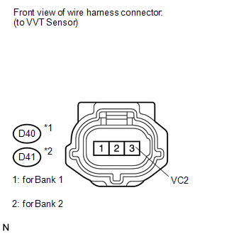
| (a) Disconnect the VVT sensor (for exhaust side) connector. |
|
(b) Measure the voltage according to the value(s) in the table below. Standard Voltage: Bank 1 |
Tester Connection | Switch condition |
Specified Condition | |
D40-3 (VC2) - Body ground |
Ignition switch ON | 4.5 to 5.0 V | Bank 2 |
Tester Connection | Switch condition |
Specified Condition | |
D41-3 (VC2) - Body ground |
Ignition switch ON | 4.5 to 5.0 V |
| NG |
 | REPAIR OR REPLACE HARNESS OR CONNECTOR |
|
OK |
 | |
| 2. |
CHECK HARNESS AND CONNECTOR (VVT SENSOR - ECM) |
(a) Disconnect the VVT sensor (for exhaust side) connector.
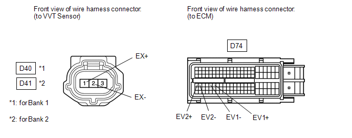 (b) Disconnect the ECM connector.
(c) Measure the resistance according to the value(s) in the table below.
Standard Resistance: |
Tester Connection | Condition |
Specified Condition | |
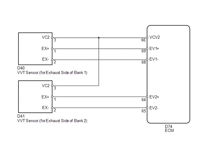
D40-1 (EX+) - D74-69 (EV1+) |
Always | Below 1 Ω | |
D40-2 (EX-) - D74-68 (EV1-) |
Always | Below 1 Ω | |
D41-1 (EX+) - D74-64 (EV2+) |
Always | Below 1 Ω | |
D41-2 (EX-) - D74-65 (EV2-) |
Always | Below 1 Ω | |
D40-1 (EX+) or D74-69 (EV1+) - Body ground |
Always | 10 kΩ or higher | |
D40-2 (EX-) or D74-68 (EV1-) - Body ground |
Always | 10 kΩ or higher | |
D41-1 (EX+) or D74-64 (EV2+) - Body ground |
Always | 10 kΩ or higher | |
D41-2 (EX-) or D74-65 (EV2-) - Body ground |
Always | 10 kΩ or higher |
| NG |
| REPAIR OR REPLACE HARNESS OR CONNECTOR |
|
OK | |
| |
| 3. |
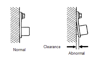
CHECK SENSOR INSTALLATION (VVT SENSOR FOR EXHAUST SIDE) |
| (a) Check the VVT sensor (for exhaust side) installation. OK:
Sensor is installed correctly. | |
| NG |
| SECURELY REINSTALL SENSOR |
|
OK | |
| |
| 4. |
INSPECT EXHAUST CAMSHAFT | (a) Check the teeth of the camshaft.
OK: Teeth do not have any cracks or deformation. HINT: Perform "Inspection After Repair" after replacing the exhaust camshaft (See page
).
| NG | |
REPLACE EXHAUST CAMSHAFT |
|
OK | |
| |
| 5. |
CHECK VALVE TIMING (CHECK FOR LOOSE OR JUMPED TEETH ON TIMING CHAIN) |
| NG | |
ADJUST VALVE TIMING |
|
OK | |
| |
| 6. |
REPLACE VVT SENSOR (FOR EXHAUST SIDE) |
(a) Replace the VVT sensor (for exhaust side) (See page
).
|
NEXT | |
| |
| 7. |
CHECK WHETHER DTC OUTPUT RECURS | (a) Connect the Techstream to the DLC3.
(b) Turn the ignition switch to ON. (c) Turn the Techstream on.
(d) Clear DTCs (See page ). (e) Refer to the confirmation driving pattern.
(f) Enter the following menus: Powertrain / Engine and ECT / Trouble Codes / Pending.
(g) Read DTCs. Result |
Display (DTC Output) | Proceed to | |
No DTC is output | A | |
P0365, P0367, P0368, P0390, P0392 or P0393 is output |
B | HINT: If the engine does not start, replace the ECM.
| A |
| END |
| B |
| REPLACE ECM | |