DTC SUMMARY |
DTC No. | Monitoring Item |
Malfunction Detection Condition |
Trouble Area | Detection Timing |
Detection Logic | |
P2610 | Soak timer (built into ECM) |
ECM internal malfunction (2 trip detection logic) |
ECM | Engine running |
2 trip | DESCRIPTION
The
soak timer operates after the ignition switch is turned off. When a
certain amount of time has elapsed after turning the ignition switch off
the soak timer activates the ECM to perform malfunction checks which
can only be performed after the engine is stopped. The soak timer is
built into the ECM. 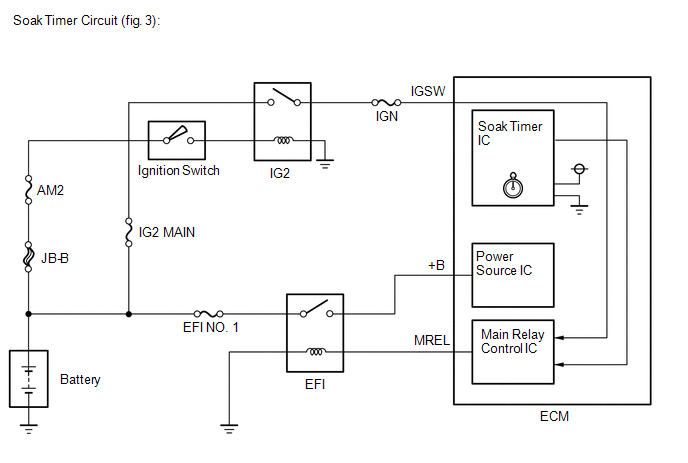 MONITOR DESCRIPTION
- While the engine is running, the ECM monitors the synchronization of the
soak timer and the CPU clock. If these two are not synchronized, the
ECM interprets this as a malfunction, illuminates the MIL and stores the
DTC.
- If the soak timer activates the ECM even though only a short amount of
time has elapsed since the ignition switch was turned off, or if the
soak timer does not activate the ECM even though a considerable amount
of time has elapsed since the ignition switch was turned off, the ECM
determines that the soak timer is malfunctioning, illuminates the MIL
and stores a DTC the next time the ignition switch is turned ON.
MONITOR STRATEGY |
Required Sensors/Components | ECM | |
Frequency of Operation | Once per driving cycle | |
Duration | 2 times: Case 1 -: Case 2 and 3 | |
MIL Operation | 2 driving cycles | |
Sequence of Operation | None | TYPICAL ENABLING CONDITIONS All |
Monitor runs whenever following DTCs are not stored |
None | Case 1 |
All of the following conditions are met |
- | | Battery voltage |
8 V or higher | | Ignition switch |
OFF | | CPU clock elapsed time |
1.96608 seconds or more | Case 2 |
All of the following conditions are met |
- | | Internal engine off timer (elapsed time from engine stop) |
10 minutes or more, and less than 30 minutes | |
Battery voltage | 8 V or higher | |
Ignition switch | ON | |
Starter | OFF | Case 3 |
All of the following conditions are met |
- | | Internal engine off timer (elapsed time from engine stop) |
40 minutes or more | | Battery voltage |
8 V or higher | | Ignition switch |
ON | | Starter |
OFF | TYPICAL MALFUNCTION THRESHOLDS Case 1 |
One of the following conditions is met | Condition A, B or C | |
A. Both of the following conditions are met |
Condition (a) and (b) | | (a) CPU clock elapsed time |
1.96608 seconds or more, and less than 8.323072 seconds | |
(b) Internal Engine off timer | 9.375 seconds or more | |
B. Both of the following conditions are met |
Condition (c) and (d) | | (c) CPU clock elapsed time |
8.323072 to 10.420224 seconds | |
(d) Internal Engine off timer | 18.75 seconds or more | |
C. Both of the following conditions are met |
Condition (e) and (f) | | (e) CPU clock elapsed time |
More than 10.420224 seconds | |
(f) Internal Engine off timer | Less than 9.375 seconds | Case 2 |
ECM started by internal engine off timer last trip |
Yes | Case 3 |
ECM started by internal engine off timer last trip |
No | CONFIRMATION DRIVING PATTERN
- Connect the Techstream to the DLC3.
- Turn the ignition switch to ON and turn the Techstream on.
- Clear DTCs (even if no DTCs are stored, perform the clear DTC operation).
- Turn the ignition switch off and wait for at least 30 seconds.
- Turn the ignition switch to ON and turn the Techstream on.
- Start the engine.
- Idle the engine for 10 minutes or more.
- Enter the following menus: Powertrain / Engine and ECT / Trouble Codes.
- Read the pending DTCs.
HINT:
- If a pending DTC is output, the system is malfunctioning.
- If a pending DTC is not output, perform the following procedure.
- Enter the following menus: Powertrain / Engine and ECT / Utility / All Readiness.
- Input the DTC: P2610.
- Check the DTC judgment result.
|
Tester Display |
Description |
|
NORMAL |
- DTC judgment completed
- System normal
|
|
ABNORMAL |
- DTC judgment completed
- System abnormal
|
|
INCOMPLETE |
- DTC judgment not completed
- Perform driving pattern after confirming DTC enabling conditions
|
|
N/A |
- Unable to perform DTC judgment
- Number of DTCs which do not fulfill DTC preconditions has reached ECU memory limit
|
HINT:
If the judgment result shows ABNORMAL, the system has a malfunction.
- If the test result is INCOMPLETE or N/A and no pending DTC is output,
perform a universal trip and check for permanent DTCs (See page
 ). ).
HINT:
- If a permanent DTC is output, the system is malfunctioning.
- If no permanent DTC is output, the system is normal.
CAUTION / NOTICE / HINT
HINT:
- DTC P2610 is stored if an internal ECM problem is detected. Diagnostic
procedures are not required. ECM replacement is necessary.
- Read freeze frame data using the Techstream. Freeze frame data records
the engine condition when malfunctions are detected. When
troubleshooting, freeze frame data can help determine if the vehicle was
moving or stationary, if the engine was warmed up or not, if the
air-fuel ratio was lean or rich, and other data from the time the
malfunction occurred.
PROCEDURE (a) Replace the ECM (See page
).
|
NEXT |
 | |
| 2. |
CHECK WHETHER DTC OUTPUT RECURS | (a) Connect the Techstream to the DLC3.
(b) Turn the ignition switch to ON. (c) Turn the Techstream on.
(d) Clear DTCs (See page ). (e) Start the engine and wait for 10 minutes or more.
(f) Enter the following menus: Powertrain / Engine and ECT / Trouble Codes / Pending.
(g) If no pending DTC is displayed, the repair has been successfully completed.
| NEXT |
 | END | |


