REMOVAL PROCEDURE 1. REMOVE TIMING CHAIN COVER SUB-ASSEMBLY (a) Remove the timing chain cover (See page 2. SET NO. 1 CYLINDER TO TDC / COMPRESSION
3. REMOVE NO. 1 CHAIN TENSIONER ASSEMBLY LH 4. REMOVE NO. 1 CHAIN TENSIONER SLIPPER LH 5. REMOVE NO. 1 CHAIN VIBRATION DAMPER LH 6. REMOVE NO. 1 CHAIN SUB-ASSEMBLY LH 7. REMOVE NO. 1 CHAIN TENSIONER ASSEMBLY RH
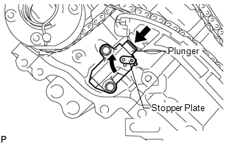
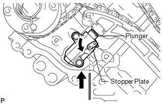
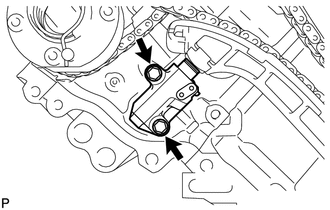
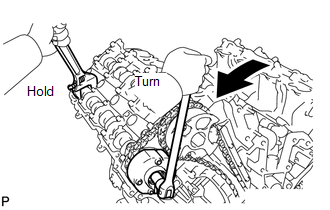
8. REMOVE NO. 1 CHAIN TENSIONER SLIPPER RH 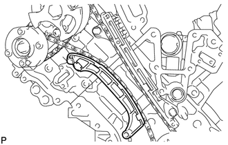 9. REMOVE NO. 1 CHAIN VIBRATION DAMPER RH 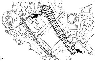 (a) Remove the 2 bolts and vibration damper. 10. REMOVE NO. 1 CHAIN SUB-ASSEMBLY RH 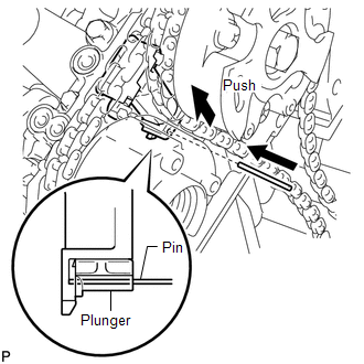 (a) While raising up the No. 2 chain tensioner, insert a pin of φ1.0 mm (0.0394 in.) into the hole to fix it in place.
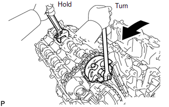
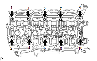
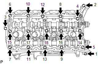
(d) Remove the 2 bolts. Then with the No. 1 and No. 2 chains still connected to the gears, remove the camshaft timing gear, camshaft timing exhaust gear and crankshaft timing sprocket RH. (e) Remove the No. 1 and No. 2 chains from the gears. 11. REMOVE NO. 2 CHAIN TENSIONER ASSEMBLY 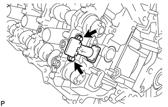 (a) Remove the 2 bolts and chain tensioner. 12. REMOVE CAMSHAFT BEARING CAP RH 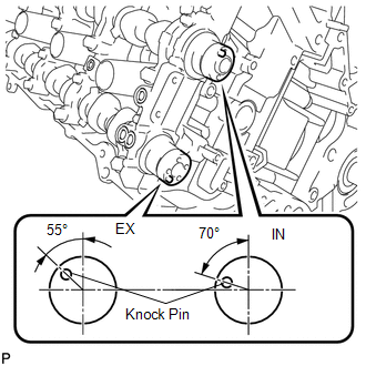 (a) Make sure that the knock pin of the camshaft is positioned as shown in the illustration.
(d) Remove the 6 bearing caps. HINT: Arrange the removed parts in the correct order. (e) Remove the No. 1 and No. 2 camshafts. 13. REMOVE CAMSHAFT HOUSING SUB-ASSEMBLY RH 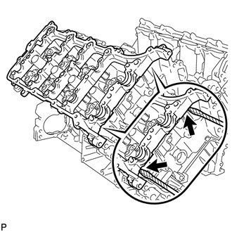 (a) Remove the camshaft housing by prying between the cylinder head and camshaft housing with a screwdriver. HINT: Tape the screwdriver tip before use. NOTICE: Be careful not to damage the contact surfaces of the cylinder head and camshaft housing. |
Toyota Tundra Service Manual > Power Tilt And Power Telescopic Steering Column System: Lost Communication with Main Body ECU (U0142,U0208)
DESCRIPTION The multiplex tilt and telescopic ECU receives signals from the main body ECU (multiplex network body ECU) and front power seat switch LH via CAN communication. DTC Code Detection Condition Trouble Area U0142 Lost communication with main body ECU (multiplex network body ECU) CAN communic ...

 ).
).