REMOVAL PROCEDURE 1. REMOVE EXHAUST MANIFOLD SUB-ASSEMBLY RH (a) Remove the exhaust manifold RH (See page 2. REMOVE CAMSHAFTS (for Bank 2) (a) Remove the camshafts (See page
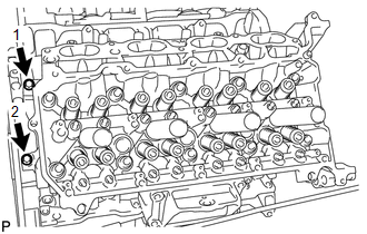
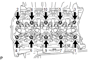
3. REMOVE NO. 1 VALVE ROCKER ARM SUB-ASSEMBLY (a) Remove the 16 valve rocker arms from the cylinder head. HINT: Arrange the removed parts in the correct order. 4. REMOVE VALVE LASH ADJUSTER ASSEMBLY (a) Remove the 16 valve lash adjusters from the cylinder head. HINT: Arrange the removed parts in the correct order. 5. REMOVE VALVE STEM CAP (a) Remove the 16 valve stem caps from the cylinder head. HINT: Arrange the removed parts in the correct order. 6. REMOVE CYLINDER HEAD SUB-ASSEMBLY RH
7. REMOVE CYLINDER HEAD GASKET RH |
Toyota Tundra Service Manual > Vehicle Stability Control System: Diagnostic Trouble Code Chart
DIAGNOSTIC TROUBLE CODE CHART Vehicle Stability Control System DTC No. Detection Item Link C1201 Engine Control System Malfunction C1225 SM Solenoid Circuit C1226 SA2 Solenoid Circuit C1227 SA3 Solenoid Circuit C1228 STR Solenoid Circuit C1234 Yaw Rate Sensor C1237 Speed Sensor Rotor Faulty C1241 Lo ...

 ).
).