INSTALLATION CAUTION / NOTICE / HINT HINT: Perform "Inspection After Repairs" after replacing the cylinder head sub-assembly RH (See page
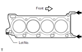
PROCEDURE 1. INSPECT CYLINDER HEAD SET BOLT 2. INSPECT CYLINDER HEAD SUB-ASSEMBLY RH 3. INSTALL CYLINDER HEAD GASKET RH (a) Check the piston protrusions for each cylinder. (1) Clean the cylinder block with solvent. (2) Set the piston of the cylinder to be measured to slightly ATDC.
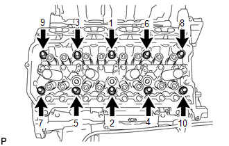
4. INSTALL CYLINDER HEAD SUB-ASSEMBLY RH HINT: Perform "Inspection After Repairs" after replacing the cylinder head sub-assembly RH (See page
(a) Place the cylinder head on the cylinder block. NOTICE:
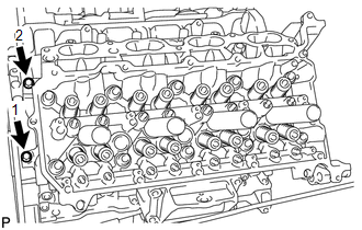
HINT: The cylinder head bolts are tightened in 3 progressive steps. (b) Apply a light coat of engine oil to the threads and under the heads of the cylinder head bolts.
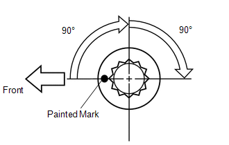
(e) Step 3: (1) Tighten the cylinder head bolts an additional 90° in the sequence shown in step 1. (2) Check that the painting marks are now facing rearward.
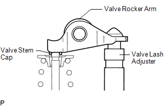
5. INSTALL VALVE STEM CAP (a) Apply a light coat of engine oil to the valve stem caps. (b) Install the 16 valve stem caps to the cylinder head. 6. INSTALL VALVE LASH ADJUSTER ASSEMBLY (a) Inspect the valve lash adjuster (See page (b) Install the 16 valve lash adjusters to the cylinder head. NOTICE: Install the lash adjuster at the same place it was removed from. 7. INSTALL NO. 1 VALVE ROCKER ARM SUB-ASSEMBLY (a) Apply engine oil to the lash adjuster tips and valve stem cap ends.
8. INSTALL CAMSHAFTS (for Bank 2) (a) Install the camshafts (See page
9. INSTALL EXHAUST MANIFOLD SUB-ASSEMBLY RH (a) Install the exhaust manifold RH (See page |
Toyota Tundra Service Manual > Touch Select 2-4 And High-low System: Four Wheel Drive (4WD) Range Signal Circuit Range / Performance (P279E)
DESCRIPTION This DTC is detected if the transfer position switch 2-4 terminal and LO terminal signals are simultaneously received. DTC Code DTC Detection Condition Diagnosis Condition Malfunction Status Malfunction Time Other Trouble Area P279E Ignition switch is ON and engine is running 2-4 termina ...

 ).
).