REMOVAL PROCEDURE 1. REMOVE V-BANK COVER SUB-ASSEMBLY 2. REMOVE NO. 1 ENGINE UNDER COVER 3. DRAIN ENGINE COOLANT 4. REMOVE INLET RADIATOR HOSE 5. REMOVE FAN AND GENERATOR V BELT 6. REMOVE FAN SHROUD
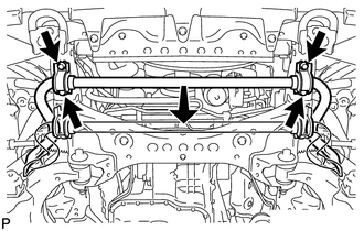
7. DISCONNECT FRONT STABILIZER BAR
8. DISCONNECT COOLER COMPRESSOR ASSEMBLY
9. REMOVE OIL PRESSURE SENDER GAUGE ASSEMBLY 10. REMOVE OIL FILTER BRACKET 11. REMOVE CRANKSHAFT PULLEY
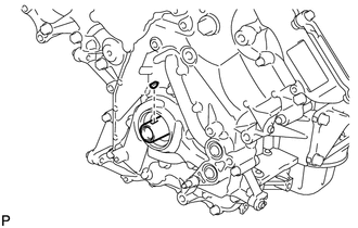
12. REMOVE CRANKSHAFT TIMING GEAR KEY
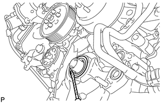
13. REMOVE FRONT CRANKSHAFT OIL SEAL
|
Toyota Tundra Service Manual > Front Power Seat Control System(w/ Memory): Reclining Sensor Malfunction (B2651)
DESCRIPTION When the position control ECU and switch assembly does not receive a sensor signal despite forward or rearward movement of the seatback by power seat motor operation, this DTC is stored. DTC Code DTC Detection Condition Trouble Area B2651 The forward and rearward lock detection position ...