INSTALLATION CAUTION / NOTICE / HINT HINT: If an exhaust gas leak has been repaired, perform an inspection following the repair (See page
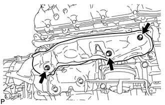
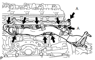
PROCEDURE 1. INSTALL EXHAUST MANIFOLD SUB-ASSEMBLY RH
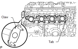
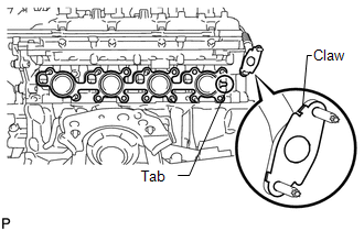
2. INSTALL NO. 1 EXHAUST MANIFOLD HEAT INSULATOR
3. INSTALL EXHAUST MANIFOLD SUB-ASSEMBLY LH
4. INSTALL NO. 2 EXHAUST MANIFOLD HEAT INSULATOR
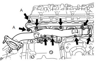
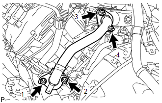
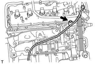
5. INSTALL NO. 1 EGR PIPE SUB-ASSEMBLY (a) Install 2 new gaskets.
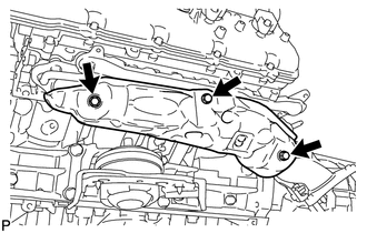
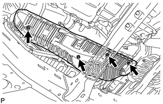
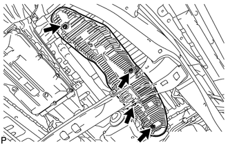
6. INSTALL FRONT NO. 3 FLOOR HEAT INSULATOR
7. INSTALL FRONT NO. 4 FLOOR HEAT INSULATOR
8. INSTALL FRONT PROPELLER SHAFT ASSEMBLY (for 4WD) (See page
9. INSTALL EXHAUST PIPE ASSEMBLY (See page 10. CONNECT COOLER COMPRESSOR ASSEMBLY 11. INSTALL GENERATOR ASSEMBLY (See page 12. INSTALL ENGINE OIL LEVEL DIPSTICK GUIDE (a) Apply a light coat of engine oil to a new O-ring. (b) Install the O-ring to the dipstick guide.
(d) Install the dipstick. 13. INSTALL INTAKE MANIFOLD (See page
14. INSPECT FOR EXHAUST GAS LEAK HINT: If an exhaust gas leak has been repaired, perform an inspection following the repair (See page
If gas is leaking, tighten the areas necessary to stop the leak. Replace damaged parts as necessary. 15. INSTALL FRONT FENDER APRON SEAL REAR LH (a) Install the fender apron seal with the 5 clips. 16. INSTALL FRONT FENDER APRON SEAL LH (a) Install the fender apron seal with the 6 clips. 17. INSTALL FRONT FENDER APRON SEAL REAR RH (a) Install the fender apron seal with the 5 clips. 18. INSTALL FRONT FENDER APRON SEAL RH (a) Install the fender apron seal with the 6 clips. |
Toyota Tundra Owners Manual > Using the driving support
systems: Intuitive parking assist
The distance from your vehicle to nearby obstacles when parallel parking or maneuvering into a garage is measured by the sensors and communicated via the multi-information display and buzzer. Always check the surrounding area when using this system. ■ Types of sensors Front corner sensors Rear co ...

 ).
).