REMOVAL PROCEDURE 1. REMOVE FRONT FENDER APRON SEAL RH (a) Remove the 6 clips and fender apron seal. 2. REMOVE FRONT FENDER APRON SEAL REAR RH (a) Remove the 5 clips and fender apron seal. 3. REMOVE FRONT FENDER APRON SEAL LH (a) Remove the 6 clips and fender apron seal. 4. REMOVE FRONT FENDER APRON SEAL REAR LH (a) Remove the 5 clips and fender apron seal. 5. REMOVE INTAKE MANIFOLD (See page 6. REMOVE GENERATOR ASSEMBLY (See page 7. DISCONNECT COOLER COMPRESSOR ASSEMBLY Click here 8. REMOVE ENGINE OIL LEVEL DIPSTICK GUIDE (a) Remove the dipstick.
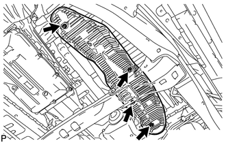
(c) Remove the O-ring from dipstick guide. 9. REMOVE EXHAUST PIPE ASSEMBLY (See page 10. REMOVE FRONT PROPELLER SHAFT ASSEMBLY (for 4WD) (See page 11. REMOVE FRONT NO. 4 FLOOR HEAT INSULATOR
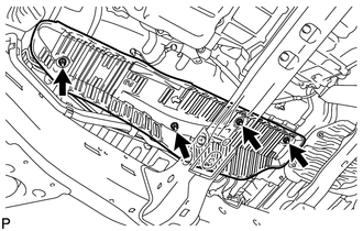
12. REMOVE FRONT NO. 3 FLOOR HEAT INSULATOR
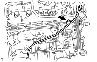
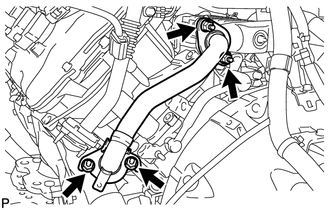
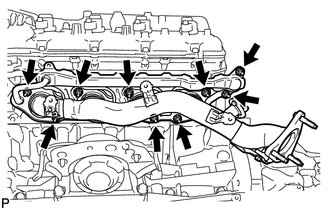
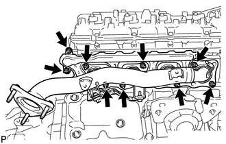
13. REMOVE NO. 1 EGR PIPE SUB-ASSEMBLY
(b) Remove the 2 gaskets. 14. REMOVE NO. 2 EXHAUST MANIFOLD HEAT INSULATOR
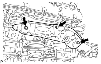
15. REMOVE EXHAUST MANIFOLD SUB-ASSEMBLY LH
16. REMOVE NO. 1 EXHAUST MANIFOLD HEAT INSULATOR
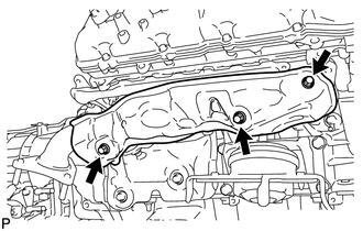
17. REMOVE EXHAUST MANIFOLD SUB-ASSEMBLY RH
|
Toyota Tundra Service Manual > Center Power Outlet Socket(for Floor Shift Type): Removal
REMOVAL PROCEDURE 1. REMOVE UPPER REAR CONSOLE PANEL SUB-ASSEMBLY 2. REMOVE UPPER CONSOLE PANEL SUB-ASSEMBLY 3. REMOVE CONSOLE BOX BEZEL (a) Disconnect the connector. (b) Using a screwdriver, detach the 5 claws and remove the console box bezel. HINT: Tape the screwdriver tip before use. Text in Illu ...

 )
)