Components COMPONENTS ILLUSTRATION 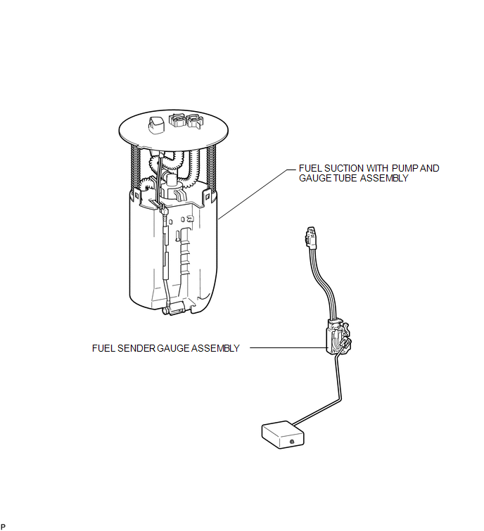 Inspection INSPECTION PROCEDURE 1. INSPECT FUEL SENDER GAUGE ASSEMBLY 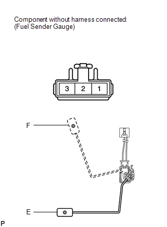 (a) Check that the float moves smoothly between F and E. (b) Measure the resistance according to the value(s) in the table below. Standard Resistance:
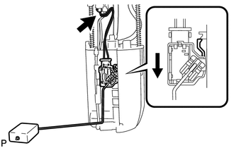
If the result is not as specified, replace the fuel sender gauge assembly. Installation INSTALLATION PROCEDURE 1. INSTALL FUEL SENDER GAUGE ASSEMBLY
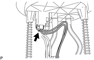
(b) Connect the fuel sender gauge connector. 2. INSTALL FUEL SUCTION WITH PUMP AND GAUGE TUBE ASSEMBLY (a) Install the fuel suction with pump and gauge tube (See page
Removal REMOVAL PROCEDURE 1. REMOVE FUEL SUCTION WITH PUMP AND GAUGE TUBE ASSEMBLY (a) Remove the fuel suction with pump and gauge tube (See page
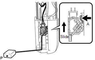
2. REMOVE FUEL SENDER GAUGE ASSEMBLY
|
Toyota Tundra Owners Manual > Multimedia: Playing an audio CD and
MP3/WMA/AAC discs
CD player operation Insert disc or select "CD" on the "Select Audio Source" screen to begin listening to a CD. Audio control screen "Select Audio Source" screen appears Audio CD: Displaying the track list MP3/WMA/AAC: Displaying the folder list Random playback Repeat play Pause Select to resume play ...