Components COMPONENTS ILLUSTRATION 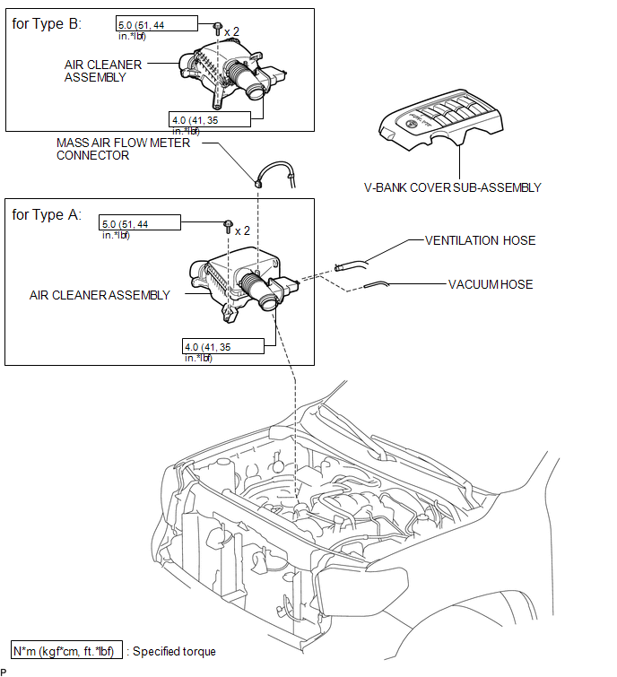 ILLUSTRATION 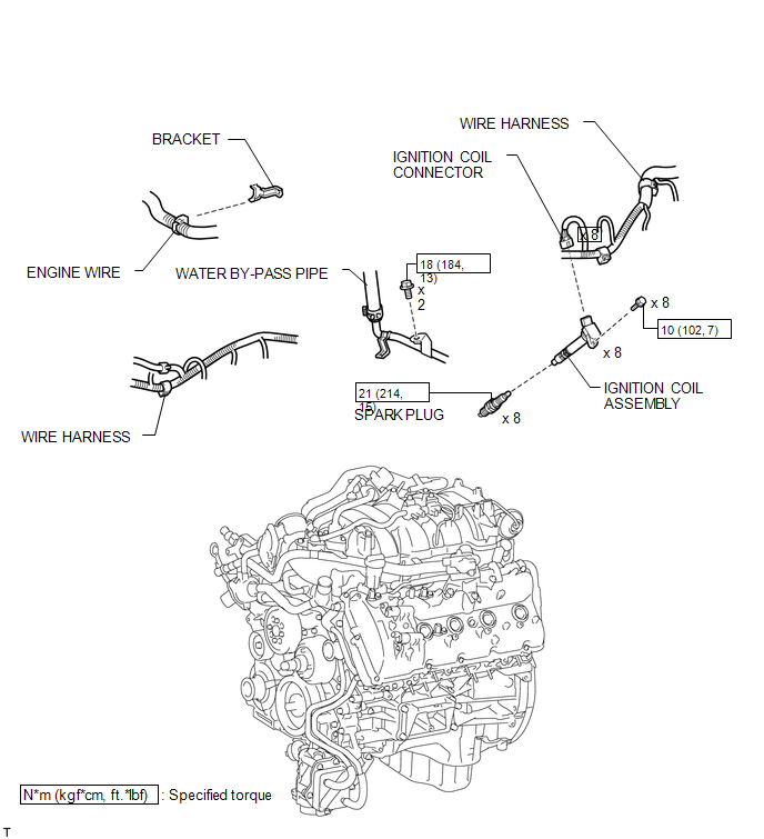 Installation INSTALLATION CAUTION / NOTICE / HINT HINT: Perform "Inspection After Repairs" after replacing the spark plug or ignition coil assembly (See page
PROCEDURE 1. INSTALL SPARK PLUG HINT: Perform "Inspection After Repairs" after replacing the spark plug (See page
(a) Using a 16 mm plug wrench, install the 8 spark plugs. Torque: 21 N·m {214 kgf·cm, 15 ft·lbf} 2. INSTALL IGNITION COIL ASSEMBLY HINT: Perform "Inspection After Repairs" after replacing the ignition coil assembly (See page
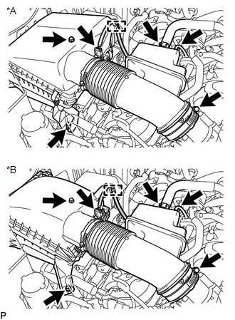
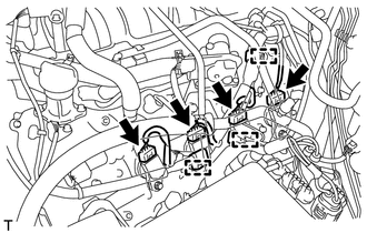
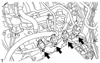
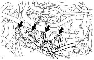
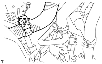
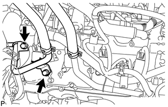
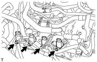
(a) for Bank 1: (1) Install the 4 ignition coil assemblies with the 4 bolts. Torque: 10 N·m {102 kgf·cm, 7 ft·lbf} (2) Connect the 4 ignition coil connectors. (3) Attach the 3 wire harness clamps. (b) for Bank 2: (1) Install the 4 ignition coil assemblies with the 4 bolts. Torque: 10 N·m {102 kgf·cm, 7 ft·lbf} (2) Attach the 2 wire harness clamps and connect the 4 ignition coil connectors. (3) Connect the water by-pass pipe with the 2 bolts. Torque: 18 N·m {184 kgf·cm, 13 ft·lbf} (4) Attach the engine wire harness clamp. 3. INSTALL AIR CLEANER ASSEMBLY (a) Install the air cleaner assembly with the 2 bolts. Torque: 5.0 N·m {51 kgf·cm, 44 in·lbf} (b) Tighten the hose clamp. Torque: 4.0 N·m {41 kgf·cm, 35 in·lbf} (c) Connect the ventilation hose and vacuum hose. (d) Attach the clamp and connect the mass air flow meter connector. 4. INSTALL V-BANK COVER SUB-ASSEMBLY Removal REMOVAL PROCEDURE 1. REMOVE V-BANK COVER SUB-ASSEMBLY 2. REMOVE AIR CLEANER ASSEMBLY
(b) Disconnect the ventilation hose and vacuum hose. (c) Loosen the hose clamp. (d) Remove the 2 bolts and air cleaner assembly. 3. REMOVE IGNITION COIL ASSEMBLY (a) for Bank 1:
(2) Disconnect the 4 ignition coil connectors.
(b) for Bank 2:
(2) Disconnect the 4 ignition coil connectors.
4. REMOVE SPARK PLUG (a) Using a 16 mm plug wrench, remove the 8 spark plugs. |
Toyota Tundra Service Manual > Air Conditioning System(for Manual Air Conditioning System): Dtc Check / Clear
DTC CHECK / CLEAR 1. CHECK DTC (a) Connect the Techstream to the DLC3. (b) Turn the ignition switch ON. (c) Turn the Techstream on. (d) Enter the following menus: Body Electrical / Air conditioner / Trouble Codes. (e) Check for DTCs. 2. CLEAR DTC (a) Connect the Techstream to the DLC3. (b) Turn the ...

 ).
).