Toyota Tundra Service Manual: Removal

REMOVAL

PROCEDURE

1. DISCHARGE FUEL SYSTEM PRESSURE

2. PRECAUTION

NOTICE:

After turning the ignition switch off, waiting time may be required before disconnecting the cable from the battery terminal. Therefore, make sure to read the disconnecting the cable from the battery terminal notice before proceeding with work (See page ).

3. DISCONNECT CABLE FROM NEGATIVE BATTERY TERMINAL

4. DRAIN ENGINE OIL

5. DRAIN ENGINE COOLANT

6. REMOVE RADIATOR ASSEMBLY

(See page )

7. REMOVE INTAKE MANIFOLD

(See page )

8. REMOVE AIR SWITCHING VALVE ASSEMBLY (for Bank 1)

9. DISCONNECT NO. 1 AIR HOSE

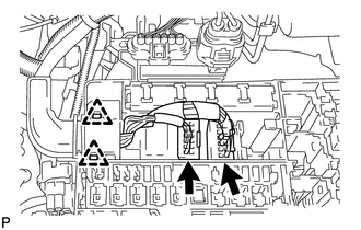
10. REMOVE AIR SWITCHING VALVE ASSEMBLY (for Bank 2)

11. DISCONNECT ENGINE WIRE

(a) Engine Room LH Side:

(1) Remove the engine room relay block cover.

(2) Disconnect the 2 connectors and detach the 2 clamps from the engine room junction block.

(3) Disconnect the 4 air injection control driver connectors.

(4) Disconnect the 2 wire harness clamps.

(5) Disconnect the injector connector.

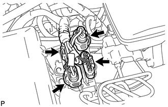
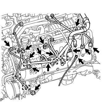
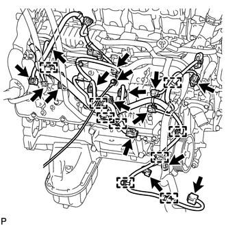
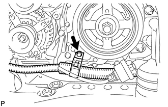
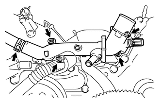
(6) Disconnect the 4 ignition coil connectors.

(7) Disconnect the 2 VVT sensor connectors.

(8) Remove the bolt and ground wire LH.

(9) Disconnect the noise filter connector.

(10) Disconnect the engine coolant temperature sensor connector.

(11) Disconnect the 2 camshaft timing oil control valve connectors.

(12) Disconnect the camshaft position sensor connector.

(13) Disconnect the 6 clamps.

(14) Disconnect the cooler compressor connector.

(b) Engine Room RH Side:

(1) Disconnect the 2 camshaft timing oil control valve connectors.

(2) Disconnect the 4 ignition coil connectors.

(3) Disconnect the injector connector.

(4) Disconnect the 2 VVT sensor connectors.

(5) Disconnect the noise filter connector.

(6) Remove the bolt and ground wire RH.

(7) Disconnect the 2 air pump connectors.

(8) Disconnect the 9 clamps.

(9) Disconnect the power steering oil pressure switch connector and solenoid valve connector.

(10) for 4WD:

Disconnect the clamp and junction connector.

(c) Remove the bolt and disconnect the wire harness clamp bracket from the timing chain cover sub-assembly.

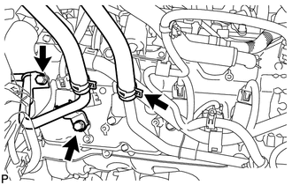
12. DISCONNECT NO. 3 AIR INJECTION SYSTEM HOSE

(a) Slide the clamp and disconnect the No. 3 air injection system hose from the air tube sub-assembly RH.

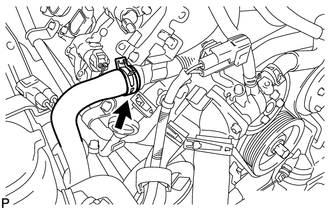
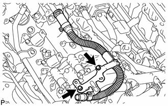
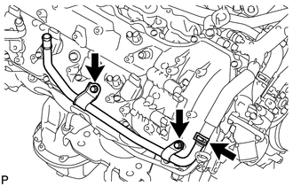
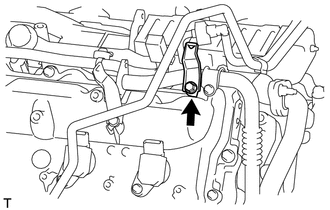
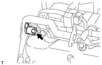
13. DISCONNECT HEATER HOSE AND NO. 1 WATER BY-PASS PIPE

(a) Slide the clamp and disconnect the heater hose from the water by-pass pipe sub-assembly.

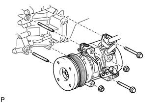
(b) Remove the 2 bolts and disconnect the No. 1 water by-pass pipe from the cylinder head cover sub-assembly RH.

14. DISCONNECT COOLER COMPRESSOR ASSEMBLY

(a) Remove the 2 bolts, 2 nuts and 2 stud bolts, and disconnect the cooler compressor assembly.

HINT:

It is not necessary to completely remove the cooler compressor assembly. With the hoses connected to the cooler compressor assembly, hang the cooler compressor assembly on the vehicle body with a rope.

15. REMOVE OIL FILTER ELEMENT

16. REMOVE OIL PRESSURE SENDER GAUGE ASSEMBLY

17. REMOVE OIL FILTER BRACKET

(a) Remove the 2 bolts, 2 nuts and oil filter bracket from the timing chain cover sub-assembly.

(b) Remove the 2 O-rings.

18. REMOVE ENGINE OIL LEVEL DIPSTICK GUIDE

19. DISCONNECT VANE PUMP ASSEMBLY

(a) Remove the 2 bolts and disconnect the vane pump assembly.

20. REMOVE GENERATOR ASSEMBLY

21. REMOVE NO. 4 ENGINE COVER

22. REMOVE NO. 3 ENGINE COVER

23. REMOVE NO. 1 WATER BY-PASS HOSE

24. REMOVE AIR TUBE SUB-ASSEMBLY RH

(a) Remove the 2 bolts and air tube sub-assembly RH from the cylinder head cover sub-assembly RH.

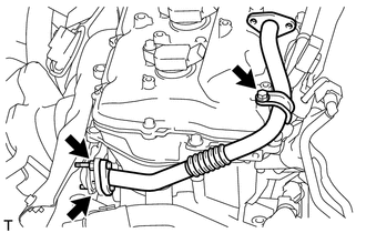
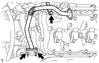
25. REMOVE WATER BY-PASS PIPE SUB-ASSEMBLY

(a) Slide the clamp and disconnect the No. 2 water by-pass hose from the water by-pass pipe sub-assembly.

(b) Remove the 2 bolts and water by-pass pipe sub-assembly from the cylinder head cover sub-assembly RH.

26. DISCONNECT NO. 8 WATER BY-PASS HOSE

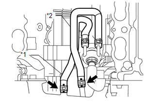
27. DISCONNECT NO. 5 WATER BY-PASS HOSE

28. REMOVE WATER INLET HOUSING

(a) Remove the 3 bolts, water inlet housing and gasket from the timing chain cover sub-assembly.

29. DISCONNECT NO. 9 WATER BY-PASS HOSE

(a) Slide the clamp and disconnect the No. 9 water by-pass hose from the front water by-pass joint.

Text in Illustration

*1

No. 9 Water By-pass Hose

*2

No. 10 Water By-pass Hose

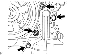
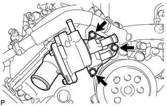
30. DISCONNECT NO. 10 WATER BY-PASS HOSE

(a) Slide the clamp and disconnect the No. 10 water by-pass hose from the front water by-pass joint.

31. REMOVE FRONT WATER BY-PASS JOINT

(a) Slide the clamp and remove the No. 2 water by-pass hose from the front water by-pass joint.

(b) Remove the 4 nuts, front water by-pass joint and 2 gaskets from the cylinder head.

32. REMOVE NO. 3 WATER BY-PASS PIPE

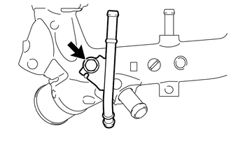
HINT:

Perform this procedure only when replacement of the No. 3 water by-pass pipe is necessary.

(a) Remove the bolt and No. 3 water by-pass pipe from the front water by-pass joint.

33. REMOVE WATER PUMP PULLEY

34. REMOVE NO. 1 IDLER PULLEY SUB-ASSEMBLY

(a) Remove the bolt and No. 1 idler pulley sub-assembly from the timing chain cover sub-assembly.

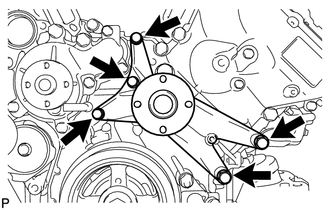
35. REMOVE FAN BRACKET ASSEMBLY

(a) Remove the 5 bolts and fan bracket assembly from the timing chain cover sub-assembly.

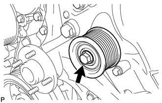
36. REMOVE V-RIBBED BELT TENSIONER ASSEMBLY

(a) Remove the bolt, 6 mm hexagon bolt and V-ribbed belt tensioner assembly from the timing chain cover sub-assembly.

37. DISCONNECT NO. 4 AIR TUBE

(a) Remove the bolt and wire harness clamp bracket from the cylinder head cover sub-assembly LH.

(b) Remove the bolt and 2 nuts, and disconnect the No. 4 air tube.

(c) Remove the gasket from the No. 4 air tube.

NOTICE:

Be careful not to damage the installation surface of the gaskets.

38. DISCONNECT NO. 3 AIR TUBE

(a) Remove the bolt and wire harness clamp bracket from the cylinder head cover sub-assembly RH.

(b) Remove the bolt and 2 nuts, and disconnect the No. 3 air tube.

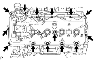
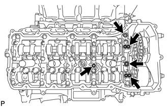
(c) Remove the gasket from the No. 3 air tube.

NOTICE:

Be careful not to damage the installation surface of the gaskets.

39. REMOVE IGNITION COIL ASSEMBLY

(a) Remove the 8 bolts and 8 ignition coils.

40. REMOVE CYLINDER HEAD COVER SUB-ASSEMBLY LH

(a) Remove the 14 bolts, seal washer, cylinder head cover sub-assembly LH and gasket.

HINT:

Make sure the removed parts are returned to the same places they were removed from.

(b) Remove the 5 gaskets from the No. 2 camshaft bearing cap and No. 3 camshaft bearing cap.

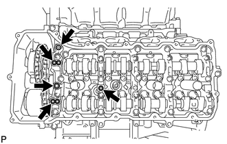
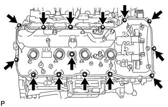
41. REMOVE CYLINDER HEAD COVER SUB-ASSEMBLY RH

(a) Remove the 14 bolts, seal washer, cylinder head cover sub-assembly RH and gasket.

HINT:

Make sure the removed parts are returned to the same places they were removed from.

(b) Remove the 5 gaskets from the No. 1 camshaft bearing cap and No. 3 camshaft bearing cap.

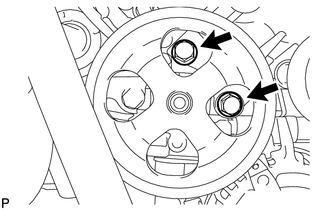
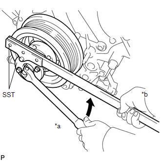
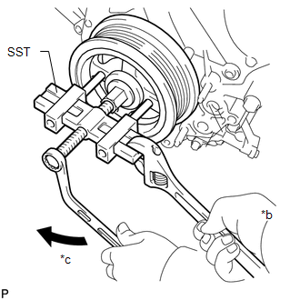
42. REMOVE CRANKSHAFT PULLEY

(a) Using SST, remove the crankshaft pulley set bolt.

SST: 09213-70011

SST: 09330-00021

Text in Illustration

*a

Turn

*b

Hold

(b) Temporarily install the crankshaft pulley set bolt to the crankshaft pulley until 2 or 3 threads are engaged.

(c) Using the crankshaft pulley set bolt and SST, remove the crankshaft pulley.

SST: 09950-50013

09951-05010

09952-05010

09953-05010

09954-05011

Text in Illustration

*a

Turn

*b

Hold

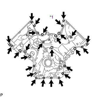
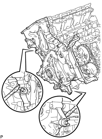
(d) Remove the crankshaft pulley set bolt and SST from the crankshaft pulley.

43. REMOVE TIMING CHAIN COVER SUB-ASSEMBLY

(a) Remove the 26 bolts and nut shown in the illustration.

Text in Illustration

*1

Nut

(b) Remove the timing chain cover sub-assembly by prying between it and the cylinder head and cylinder block with a screwdriver as shown in the illustration.

NOTICE:

Be careful not to damage the cylinder head and cylinder block contact surfaces of the timing chain cover sub-assembly.

HINT:

Tape the screwdriver tip before use.

(c) Remove the oil pump gasket from the cylinder block.

(d) Remove the O-ring from the oil pan sub-assembly.

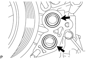
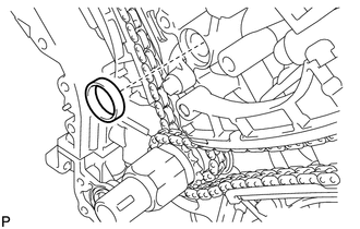
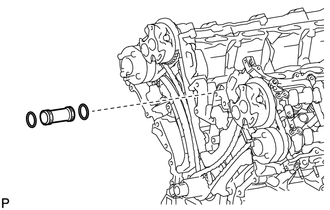
44. REMOVE WATER INLET PIPE

(a) Remove the water inlet pipe from the No. 1 heat exchanger cover.

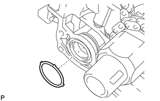
(b) Remove the 2 O-rings from the water inlet pipe.

45. REMOVE FRONT CRANKSHAFT OIL SEAL

    Reassembly

    1ur-fe Starting

    See More:

    Toyota Tundra Service Manual > Vehicle Stability Control System: Freeze Frame Data
    FREEZE FRAME DATA FREEZE FRAME DATA (a) Whenever an ABS DTC is detected, the skid control ECU (brake actuator assembly) stores the current vehicle (ECU or sensor) state as Freeze Frame Data. (b) The skid control ECU (brake actuator assembly) stores the number of times (maximum: 31) the ignition swit ...

    Toyota Tundra Owners Manual

    Toyota Tundra Service Manual

    © 2024 Copyright www.ttundra.com
    0.0134