REMOVAL PROCEDURE 1. PRECAUTION NOTICE: After
turning the ignition switch off, waiting time may be required before
disconnecting the cable from the battery terminal. Therefore, make sure
to read the disconnecting the cable from the battery terminal notice
before proceeding with work (See page 2. DISCONNECT CABLE FROM NEGATIVE BATTERY TERMINAL 3. REMOVE EXHAUST MANIFOLD SUB-ASSEMBLY RH (a) Remove the exhaust manifold RH (See page
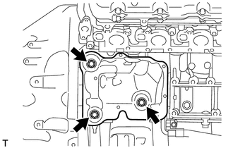
4. REMOVE STARTER COVER
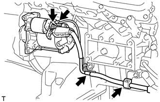
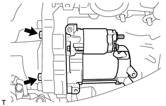
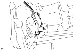
5. REMOVE STARTER ASSEMBLY
(b) Disconnect the starter connector. (c) Remove the nut and disconnect the starter wire.
|
Toyota Tundra Service Manual > Power Window Control System(w/o Jam Protection Function): Rear Power Window RH does not Operate with Rear Power Window Switch RH
DESCRIPTION HINT: for Double Cab, CrewMax If the rear RH side manual UP/DOWN function does not operate, there may be a malfunction in the rear switch RH, rear motor RH, master switch or harness and connector. WIRING DIAGRAM PROCEDURE 1. CHECK HARNESS AND CONNECTOR (REAR SWITCH RH - BATTERY) (a) Disc ...