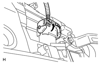
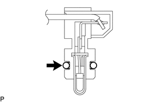
INSTALLATION PROCEDURE 1. INSTALL TRANSMISSION WIRE (a) Coat a new O-ring with ATF, and install it to the transmission wire connector.
2. CONNECT TRANSMISSION WIRE 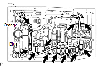
(a) Connect the 9 solenoid valve connectors.
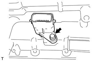
(c) Connect the 2 ATF temperature sensors with the 2 clamps and 2 bolts. Torque: for bolt A : 10 N·m {102 kgf·cm, 7 ft·lbf} for bolt B : 11 N·m {112 kgf·cm, 8 ft·lbf} HINT: Each bolt length is indicated below. 12 mm (0.472 in.) for bolt A 36 mm (1.41 in.) for bolt B (d) Attach the wire harness to the 2 clamps. 3. INSTALL VALVE BODY OIL STRAINER ASSEMBLY 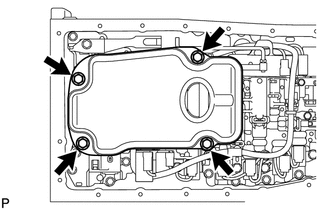 (a) Coat a new O-ring with ATF, and install it to the oil strainer. (b) Install the oil strainer with the 4 bolts. Torque: 10 N·m {102 kgf·cm, 7 ft·lbf} 4. INSTALL AUTOMATIC TRANSMISSION OIL PAN SUB-ASSEMBLY 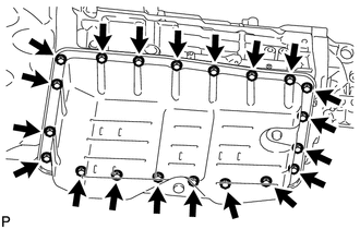 NOTICE: Be careful not to spill oil on the contacting surfaces of the transmission case and oil pan. (a) Install a new gasket and the oil pan with the 20 bolts. Torque: 7.0 N·m {71 kgf·cm, 62 in·lbf} 5. ADD AUTOMATIC TRANSMISSION FLUID (a) Add automatic transmission fluid (See page
|
Toyota Tundra Service Manual > Occupant Classification System: Diagnostic Trouble Code Chart
DIAGNOSTIC TROUBLE CODE CHART HINT: When DTC B1650/32 is detected as a result of troubleshooting for the "AIRBAG SYSTEM", perform troubleshooting for the "OCCUPANT CLASSIFICATION SYSTEM" as shown in the chart below. Use the Techstream to read and clear the DTC of the occupant cla ...