INSTALLATION CAUTION / NOTICE / HINT HINT:
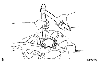
PROCEDURE 1. INSTALL KNUCKLE GREASE RETAINER CAP LH (for 2WD)
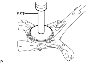
2. INSTALL STEERING KNUCKLE OIL SEAL LH
3. INSTALL STEERING KNUCKLE LH (a) Install the front suspension upper arm to the steering knuckle with the nut. Torque: 110 N·m {1122 kgf·cm, 81 ft·lbf} (b) Install a new clip. HINT: If the holes for the clip are not aligned, tighten the nut up to another 60. 4. CONNECT FRONT LOWER BALL JOINT ATTACHMENT LH
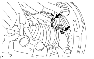
5. CONNECT TIE ROD END SUB-ASSEMBLY LH 6. INSTALL FRONT AXLE HUB SUB-ASSEMBLY LH (a) Install the front axle hub (see page 7. CONNECT FRONT SPEED SENSOR LH
(b) Attach the clip to the steering knuckle. 8. INSTALL FRONT WHEEL Torque: for Aluminum Wheel : 131 N·m {1336 kgf·cm, 97 ft·lbf} for Steel Wheel : 209 N·m {2131 kgf·cm, 154 ft·lbf} 9. CHECK SPEED SENSOR SIGNAL (a) Check the speed sensor signal (see page 10. CHECK SRS WARNING LIGHT (a) Check the SRS warning light (see page
11. INSPECT AND ADJUST FRONT WHEEL ALIGNMENT (a) Inspect and adjust the front wheel alignment (see page
|
Toyota Tundra Service Manual > Theft Deterrent System: Horn Circuit
DESCRIPTION When the theft deterrent system is switched from the armed state to the alarm sounding state, the main body ECU (multiplex network body ECU) transmits a signal to cause the horn to sound at intervals of 0.4 seconds. WIRING DIAGRAM CAUTION / NOTICE / HINT NOTICE: Inspect the fuses for cir ...