REMOVAL CAUTION / NOTICE / HINT HINT:
PROCEDURE 1. REMOVE FRONT AXLE HUB SUB-ASSEMBLY LH (a) Remove the front axle hub (see page 2. DISCONNECT FRONT SPEED SENSOR LH
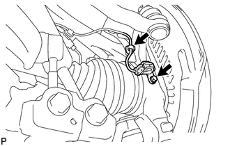
(b) Disconnect the speed sensor from the steering knuckle. 3. DISCONNECT TIE ROD END SUB-ASSEMBLY LH (a) Remove the cotter pin and nut.
4. DISCONNECT FRONT LOWER BALL JOINT ATTACHMENT LH
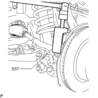
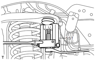
5. REMOVE STEERING KNUCKLE LH (a) Support the front suspension lower arm LH with a jack. (b) Remove the clip and the nut.
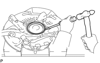
(d) Remove the steering knuckle. 6. REMOVE KNUCKLE GREASE RETAINER CAP LH (for 2WD)
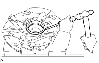
7. REMOVE STEERING KNUCKLE OIL SEAL LH (for 4WD)
|
Toyota Tundra Service Manual > Seat Heater System: System Description
SYSTEM DESCRIPTION 1. GENERAL (a) By operating the seat heater switch, which is located in the air conditioning control assembly, the temperature is controlled to 3 settings. LOWEST: 32.5°C (90.5°F) MID: 44.5°C (112.1°F) HIGH: 58.25°C (136.85°F) (b) Whether the seat heater is on or off can be ...

 ).
).