DESCRIPTION The cruise
control main switch is used to turn the dynamic radar cruise control
system on and off, as well as operate 7 functions: SET, - (COAST),
TAP-DOWN, RES (RESUME), + (ACCEL), TAP-UP and CANCEL. The
SET, TAP-DOWN and - (COAST) functions, and the RES (RESUME), TAP-UP and
+ (ACCEL) functions are operated with the same switch. The cruise
control main switch contains momentary type contacts for each function.
The contacts close only while the cruise control main switch is being
operated in the direction of the relative function arrow, and open when
the cruise control main switch is released. The voltage at the terminal
of the hybrid vehicle control ECU assembly changes as each of the
different contacts open or close. The hybrid vehicle control ECU
assembly reads this voltage and controls the SET, - (COAST), RES
(RESUME), + (ACCEL), and CANCEL functions accordingly.
- Vehicle-to-vehicle distance control mode is selected by default when the
dynamic radar cruise control system is turned on using the cruise
control main switch (ON-OFF button).
- The operation of constant speed control mode is the same as that for a conventional cruise control system.
WIRING DIAGRAM
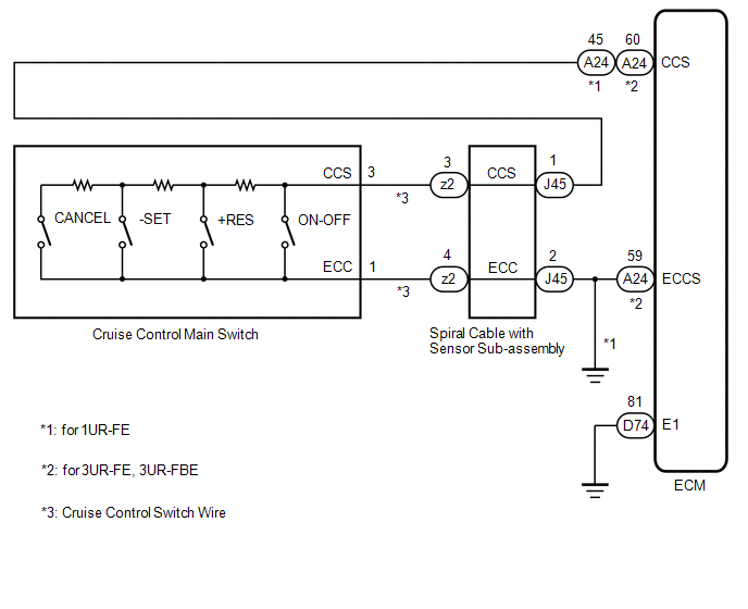
CAUTION / NOTICE / HINT
NOTICE:
- Before replacing the ECM, refer to Registration.
Click here
- The vehicle is equipped with a Supplemental Restraint System (SRS) which
includes components such as airbags. Before servicing (including
removal or installation of parts), be sure to read the precaution for
Supplemental Restraint System.
Click here
PROCEDURE |
1. | READ VALUE ON TECHSTREAM |
(a) Connect the Techstream to the DLC3. (b) Turn the ignition switch to ON.
(c) Turn the Techstream on. (d) Enter the following menus: Powertrain / Radar Cruise1 / Data List.
(e) Read the Data List according to the display on the Techstream. Powertrain > Radar Cruise1 > Data List |
Tester Display | Measurement Item |
Range | Normal Condition |
Diagnostic Note | |
Cancel Switch | CANCEL switch status |
ON or OFF | ON: CANCEL switch on
OFF: CANCEL switch off |
- | | -SET Switch |
-SET switch status | ON or OFF |
ON: -SET switch on OFF: -SET switch off |
- | | +RES Switch |
+RES switch status | ON or OFF |
ON: +RES switch on OFF: +RES switch off |
- | | Cruise Main Switch Operation Condition |
Cruise control main switch (ON-OFF button) status |
ON or OFF | ON: Cruise control main switch (ON-OFF button) pushed
OFF: Cruise control main switch (ON-OFF button) not pushed |
- | OK: The Data List items shown in the table change according to the operation of the cruise control main switch.
| OK |
| PROCEED TO NEXT SUSPECTED AREA SHOWN IN PROBLEM SYMPTOMS TABLE |
|
NG |
| |
| 2. |
INSPECT CRUISE CONTROL MAIN SWITCH | (a) Remove the cruise control main switch.
Click here (b) Inspect the cruise control main switch.
Click here
| NG |
| REPLACE CRUISE CONTROL MAIN SWITCH |
|
OK |
| |
| 3. |
CHECK CRUISE CONTROL SWITCH WIRE |
| (a) Remove the cruise control switch wire. Click here
|
|
|
*1 | Cruise Control Switch Wire | |
*a | Front view of wire harness connector
(to Spiral Cable with Sensor Sub-assembly) | |
*b | Front view of wire harness connector
(to Cruise Control Main Switch) | | |
(b) Measure the resistance according to the value(s) in the table below.
Standard Resistance (Check for Open): |
Tester Connection | Specified Condition | |
Cruise control main switch side connector terminal 3 - z2-3 |
Below 1 Ω | |
Cruise control main switch side connector terminal 1 - z2-4 |
Below 1 Ω |
| NG |
| REPLACE CRUISE CONTROL SWITCH WIRE |
|
OK |
| |
| 4. |
INSPECT SPIRAL CABLE WITH SENSOR SUB-ASSEMBLY |
(a) Remove the spiral cable with sensor sub-assembly. Click here
(b) Inspect the spiral cable with sensor sub-assembly.
Click here
| NG |
| REPLACE SPIRAL CABLE WITH SENSOR SUB-ASSEMBLY |
|
OK |
| |
| 5. |
CHECK HARNESS AND CONNECTOR (SPIRAL CABLE WITH SENSOR SUB-ASSEMBLY - ECM AND BODY GROUND) |
(a) Disconnect the J45 spiral cable with sensor sub-assembly connector.
(b) Disconnect the A24 ECM connector. (c) Measure the resistance according to the value(s) in the table below.
Standard Resistance (1UR-FE): |
Tester Connection | Condition |
Specified Condition | |
J45-1 (CCS) - A24-45 (CCS) |
Always | Below 1 Ω | |
J45-2 (ECC) - Body ground |
Always | Below 1 Ω | |
J45-1 (CCS) or A24-45 (CCS) - Body ground |
Always | 10 kΩ or higher |
Standard Resistance (3UR-FE, 3UR-FBE): |
Tester Connection | Condition |
Specified Condition | |
J45-1 (CCS) - A24-60 (CCS) |
Always | Below 1 Ω | |
J45-2 (ECC) - A24-59 (ECCS) |
Always | Below 1 Ω | |
J45-1 (CCS) or A24-60 (CCS) - Body ground |
Always | 10 kΩ or higher | |
J45-2 (ECC) - A24-59 (ECCS) - Body ground |
Always | 10 kΩ or higher |
| NG |
| REPAIR OR REPLACE HARNESS OR CONNECTOR |
|
OK |
| |
| 6. |
CHECK HARNESS AND CONNECTOR (ECM - BODY GROUND) |
(a) for 1UR-FE: Disconnect the J45 spiral cable with sensor sub-assembly connector.
(b) for 3UR-FE, 3UR-FBE: Disconnect the D74 ECM connector. (c) Measure the resistance according to the value(s) in the table below.
Standard Resistance (for 1UR-FE): |
Tester Connection | Condition |
Specified Condition | |
J45-2 (ECC) - Body ground |
Always | Below 1 Ω |
Standard Resistance (for 3UR-FE, 3UR-FBE): |
Tester Connection | Condition |
Specified Condition | |
D74-81 (E1) - Body ground |
Always | Below 1 Ω |
| OK |
| REPLACE ECM |
| NG |
| REPAIR OR REPLACE HARNESS OR CONNECTOR | |