Toyota Tundra Service Manual: Parts Location

PARTS LOCATION

ILLUSTRATION
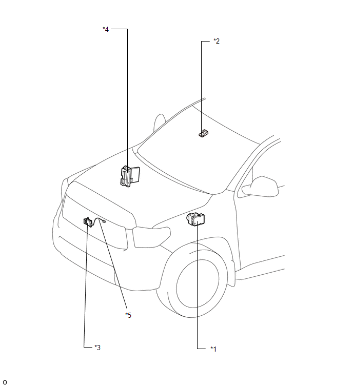
*1

SKID CONTROL ECU (BRAKE ACTUATOR ASSEMBLY)

*2

FORWARD RECOGNITION CAMERA

*3

MILLIMETER WAVE RADAR SENSOR ASSEMBLY

*4

ECM

*5

MILLIMETER WAVE RADAR WIRE

-

-

ILLUSTRATION

*1

STEERING PAD SWITCH ASSEMBLY

  • LANE DEPARTURE ALERT MAIN SWITCH
  • CUSTOMIZE SWITCH

*2

YAW RATE AND ACCELERATION SENSOR (AIRBAG SENSOR ASSEMBLY)

*3

DRIVER SIDE JUNCTION BLOCK

  • ECU-IG1 NO. 4 FUSE

*4

MAIN BODY ECU (MULTIPLEX NETWORK BODY ECU)

*5

SPIRAL WITH SENSOR CABLE SUB-ASSEMBLY

*6

COMBINATION METER ASSEMBLY

*7

NETWORK GATEWAY ECU

-

-

    Operation Check

    Power Source Circuit

    See More:

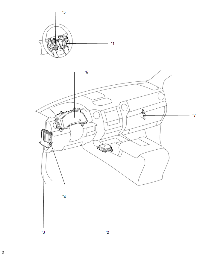
    Toyota Tundra Service Manual > Blind Spot Monitor System: Operation Check
    OPERATION CHECK HINT: The blind spot monitor beam axis confirmation is performed to confirm whether the sensor's beam axis is correct, and perform adjustment of the beam axis by using reflector. BLIND SPOT MONITOR BEAM AXIS CONFIRMATION (a) When performing the blind spot monitor beam axis confirmati ...

    Toyota Tundra Owners Manual

    Toyota Tundra Service Manual

    © 2026 Copyright www.ttundra.com
    0.0268