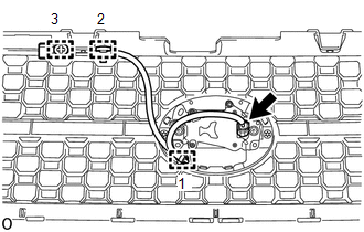
INSTALLATION CAUTION / NOTICE / HINT NOTICE: If the millimeter wave radar sensor assembly has been struck or dropped, replace the millimeter wave radar sensor assembly with a new one. PROCEDURE 1. INSTALL MILLIMETER WAVE RADAR SENSOR ASSEMBLY (a) for Type A: 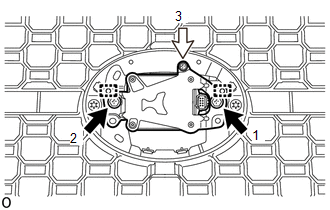
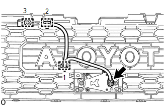
(1) Attach the 2 guides. (2) Temporarily install the millimeter wave radar sensor assembly with the 2 bolts and screw. (3) Tighten the 2 bolts and screw in the order shown in the illustration. Torque: Bolt : 2.5 N·m {25 kgf·cm, 22 in·lbf} (b) for Type B: 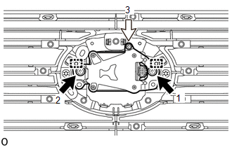
(1) Attach the 2 guides. (2) Temporarily install the millimeter wave radar sensor assembly with the 2 bolts and screw. (3) Tighten the 2 bolts and screw in the order shown in the illustration. Torque: Bolt : 2.5 N·m {25 kgf·cm, 22 in·lbf} (c) for Type C: 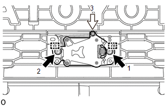
(1) Attach the 2 guides. (2) Temporarily install the millimeter wave radar sensor assembly with the 2 bolts and screw. (3) Tighten the 2 bolts and screw in the order shown in the illustration. Torque: Bolt : 2.5 N·m {25 kgf·cm, 22 in·lbf} 2. INSTALL MILLIMETER WAVE RADAR WIRE
3. INSTALL RADIATOR GRILLE Click here 4. ADJUST MILLIMETER WAVE RADAR SENSOR ASSEMBLY (a) When the millimeter wave radar sensor assembly is replaced, adjust the millimeter wave radar sensor assembly. Click here |
Toyota Tundra Service Manual > Propeller Shaft Assembly(for 4wd): Disassembly
DISASSEMBLY PROCEDURE 1. REMOVE REAR PROPELLER SHAFT UNIVERSAL JOINT SPIDER BEARING (a) Place matchmarks on the propeller shaft yoke and universal joint yoke. Text in Illustration *a Matchmark (b) Remove the grease fitting from the spider bearing. (c) Using a brass bar and hammer, slightly tap in th ...