Toyota Tundra Service Manual: Disassembly

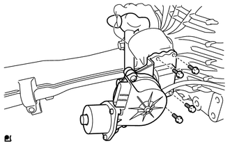
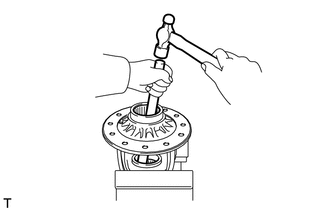
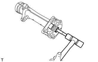
DISASSEMBLY

PROCEDURE

1. REMOVE AUTOMATIC DISCONNECTING DIFFERENTIAL ACTUATOR

(a) Remove the 4 bolts.

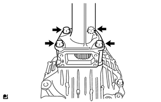
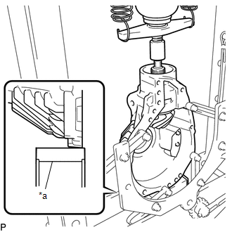
(b) Using a hammer handle, remove the actuator.

2. REMOVE FRONT DIFFERENTIAL TUBE ASSEMBLY

(a) Remove the 4 bolts.

(b) Using a plastic-faced hammer, remove the differential tube.

3. REMOVE DIFFERENTIAL SIDE GEAR SHAFT OIL SEAL

(a) Using SST, tap out the oil seal.

SST: 09308-00010

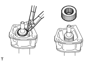
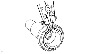
4. REMOVE DIFFERENTIAL SIDE GEAR INTER SHAFT SUB-ASSEMBLY

(a) Using SST, remove the side gear inter shaft.

SST: 09350-20015

09369-20040

SST: 09950-40011

09951-04010

09952-04010

09953-04020

09954-04010

09955-04011

09957-04010

09958-04011

Text in Illustration

*a

Turn

*b

Hold

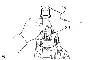
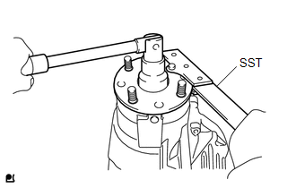
(b) Remove the snap ring from the side gear inter shaft.

5. REMOVE FRONT DRIVE PINION COMPANION FLANGE FRONT NUT

(a) Using SST and a hammer, unstake the nut.

SST: 09930-00010

(b) Using SST to hold the companion, remove the nut.

SST: 09330-00021

09330-00030

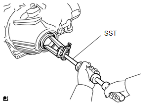
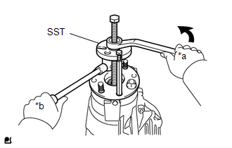
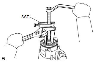
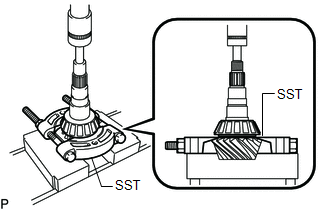
6. REMOVE FRONT DRIVE PINION COMPANION FLANGE SUB-ASSEMBLY

(a) Using SST, remove the companion flange from the differential carrier.

SST: 09950-30012

09951-03010

09953-03010

09954-03010

09955-03030

09956-03020

Text in Illustration

*a

Turn

*b

Hold

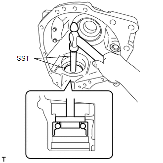
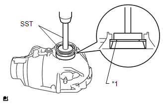
7. REMOVE FRONT DIFFERENTIAL CARRIER OIL SEAL

(a) Using SST, remove the oil seal.

SST: 09308-10010

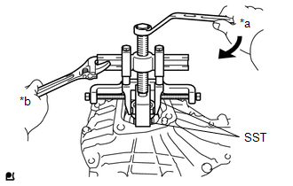
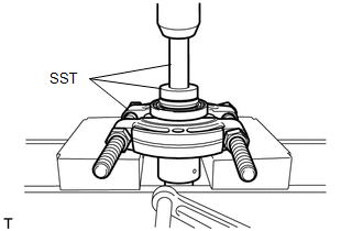
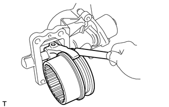
8. REMOVE FRONT DIFFERENTIAL DRIVE PINION OIL SLINGER

9. REMOVE FRONT DIFFERENTIAL CROSS SHAFT BEARING RETAINER

(a) Remove the bolts B and front differential front support assembly LH.

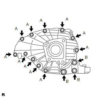
(b) Remove the bolts A.

(c) Using a plastic-faced hammer, tap out the bearing retainer.

10. REMOVE DIFFERENTIAL CASE ASSEMBLY

(a) Remove the differential case from the differential carrier.

11. REMOVE DIFFERENTIAL DRIVE PINION

(a) Set the differential carrier to an overhaul stand as shown in the illustration.

Text in Illustration

*a

Block

(b) Using a press, press out the drive pinion.

NOTICE:

Do not drop the drive pinion.

12. REMOVE FRONT DRIVE PINION FRONT RADIAL BALL BEARING

(a) Remove the bearing (inner race) from the differential carrier.

13. REMOVE FRONT DIFFERENTIAL DRIVE PINION BEARING SPACER

14. REMOVE FRONT DIFFERENTIAL BREATHER PLUG OIL DEFLECTOR

(a) Remove the 2 bolts and oil deflector.

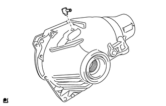
15. REMOVE FRONT DIFFERENTIAL UNION

(a) Remove the front differential union from the differential carrier.

16. REMOVE FRONT DRIVE PINION REAR TAPERED ROLLER BEARING

(a) Using SST and a press, press out the bearing (inner race).

SST: 09950-00020

If the drive gear or ring gear is damaged, replace them as a set.

17. REMOVE FRONT DRIVE PINION REAR TAPERED ROLLER BEARING

(a) Using a brass bar and hammer, tap out the bearing (outer race) and washer.

18. REMOVE FRONT DRIVE PINION FRONT RADIAL BALL BEARING

(a) Using SST and hammer, tap out the bearing (outer race).

SST: 09950-70010

09951-07100

SST: 09950-60010

09951-00450

SST: 09950-60020

09951-00710

09952-06010

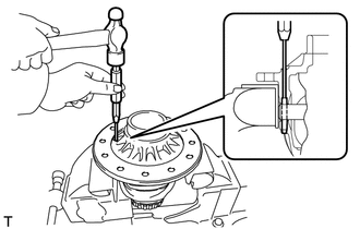
19. REMOVE FRONT DIFFERENTIAL CASE BEARING

HINT:

  • Measure the plate washer and note its thickness.
  • Tag the bearing outer races to show the location for reassembly.

(a) Using SST and a press, press out the bearing (outer race) and plate washer from the bearing retainer.

SST: 09950-60020

09951-00680

SST: 09950-70010

09951-07150

Text in Illustration

*1

Plate Washer

(b) Using SST and a press, press out the bearing (outer race) and plate washer from the differential carrier.

SST: 09950-60020

09951-00680

SST: 09950-70010

09951-07150

Text in Illustration

*1

Plate Washer

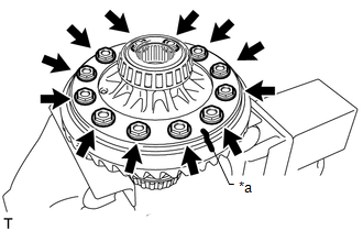
20. REMOVE DIFFERENTIAL RING GEAR

(a) Place matchmarks on the ring gear and differential case.

Text in Illustration

*a

Matchmark

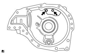
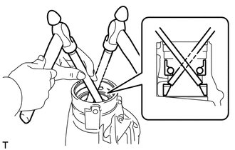
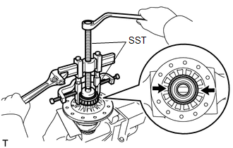
(b) Remove the 12 bolts.

(c) Using a plastic-faced hammer, tap on the ring gear to separate it from the differential case.

21. REMOVE FRONT DIFFERENTIAL CASE BEARING

(a) Using SST, remove the 2 bearings (inner race).

SST: 09950-60010

09951-00550

SST: 09950-40011

09951-04020

09952-04010

09953-04030

09954-04010

09955-04061

09957-04010

09958-04011

HINT:

Fix the claws of SST into the notch in the differential case assembly.

22. DISASSEMBLE DIFFERENTIAL CASE

(a) Using a pin punch and hammer, tap out the straight pin.

(b) Remove these parts from the differential case assembly.

(1) 2 differential side gears

(2) 2 differential side gear thrust washers

(3) Differential pinion shaft

(4) 2 differential pinion gears

(5) 2 differential pinion gear thrust washers

23. INSPECT DIFFERENTIAL GEAR KIT

(a) Check that there is no damage to the pinion gear and side gear.

If the pinion gear and/or side gear is damaged, replace the differential gear kit.

24. INSPECT FRONT DIFFERENTIAL CASE

(a) Check that the differential case is not damaged.

If the differential case is damaged, replace it.

25. REMOVE FRONT DIFFERENTIAL SIDE GEAR NEEDLE ROLLER BEARING

(a) Using a brass bar and hammer, tap out the 2 bearings.

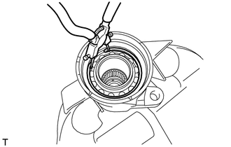
26. REMOVE DIFFERENTIAL CLUTCH HUB

(a) Remove the differential clutch sleeve.

(b) Using a snap ring expander, remove the snap ring.

(c) Remove the differential clutch hub.

27. REMOVE DIFFERENTIAL SIDE GEAR SHAFT OIL SEAL

(a) Using SST, tap out the oil seal.

SST: 09308-00010

28. REMOVE DIFFERENTIAL SIDE GEAR SHAFT SUB-ASSEMBLY RH

(a) Using a snap ring expander, remove the snap ring.

(b) Using a plastic-faced hammer, tap out the side gear shaft.

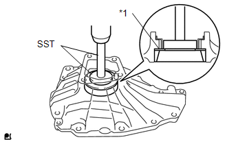
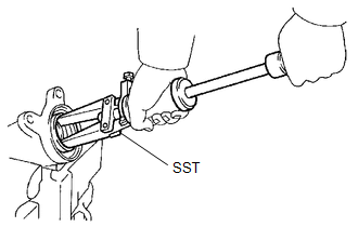
29. REMOVE FRONT DIFFERENTIAL SIDE GEAR SHAFT RH BEARING

(a) Using a snap ring expander, remove the snap ring.

(b) Using SST, a brass bar and press, press out the bearing.

SST: 09950-00020

SST: 09950-70010

09951-07100

SST: 09950-60010

09951-00450

NOTICE:

Do not damage the bearing.

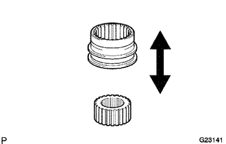
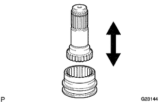
30. INSPECT DIFFERENTIAL CLUTCH SLEEVE AND DIFFERENTIAL CLUTCH HUB

(a) Check for wear and damage to the clutch hub and clutch sleeve.

If necessary, replace them.

(b) Check that the clutch sleeve slides smoothly on the clutch hub.

31. INSPECT DIFFERENTIAL CLUTCH SLEEVE AND DIFFERENTIAL SIDE GEAR INTER SHAFT

(a) Check for wear and damage to the clutch hub and side gear inter shaft.

(b) Check that the clutch sleeve slides smoothly on the side gear inter shaft.

32. INSPECT DIFFERENTIAL CLUTCH SLEEVE AND CLUTCH SLEEVE FORK CLEARANCE

(a) Using a feeler gauge, measure the clearance between the sleeve fork and clutch sleeve.

Maximum clearance:

0.35 mm (0.0138 in.)

If the clearance exceeds the maximum, replace the fork or clutch sleeve.

    Components

    Installation

    See More:

    Toyota Tundra Service Manual > Sliding Roof System: Initialization
    INITIALIZATION 1. INITIALIZE SLIDING ROOF DRIVE GEAR SUB-ASSEMBLY NOTICE: When replacing the sliding roof drive gear, the new sliding roof drive gear requires initialization. If a reset is not executed, the following functions do not operate: AUTO operation and jam protection function. (a) Turn the ...

    Toyota Tundra Owners Manual

    Toyota Tundra Service Manual

    © 2024 Copyright www.ttundra.com
    0.0104