REASSEMBLY PROCEDURE 1. INSTALL PROPELLER SHAFT UNIVERSAL JOINT SPIDER BEARING
HINT: Use the same installation procedure for both the sleeve yoke side and flange yoke side universal joint spider bearings.
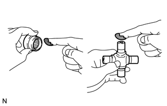
| (a) Apply MP grease to a new spider and 4 new bearings. NOTICE:
Be careful not to apply too much grease. | |
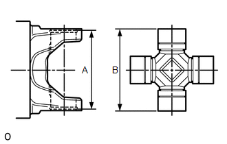
| (b) Measure dimension A between the snap ring grooves. |
|
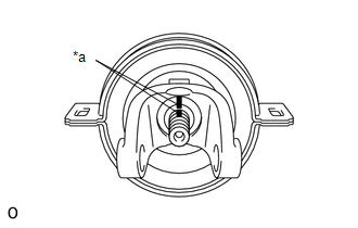
(c) Install the 4 spider bearings to the spider journal portions, and then measure dimension B of the universal joint.
NOTICE: When measuring dimension B, fix the spider and spider bearings in a vise and hold them firmly together.
| (d) Select snap rings to make dimensions A and B the same. Hole Snap Ring Thickness: |
Color | Thickness | |
Black | 1.49 mm (0.0586 in.) | |
Copper | 1.51 mm (0.0594 in.) | |
White | 1.56 mm (0.0614 in.) | |
Blue | 1.64 mm (0.0646 in.) | |
Black | 1.52 mm (0.0598 in.) | |
Black | 1.54 mm (0.0606 in.) | |
Black | 1.62 mm (0.0638 in.) |
NOTICE:
- Use new snap rings.
- If possible, use snap rings of the same thickness for both sides.
| |
(e) Temporarily install the spider and 2 universal joint spider bearings into the sleeve yoke.
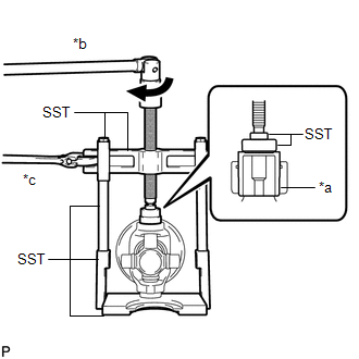
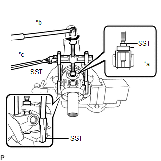
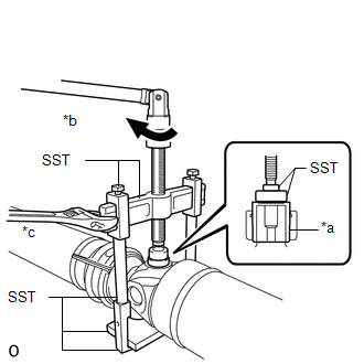
| (f) Using SST, press the universal joint spider bearing into the universal joint sleeve yoke until the groove can be seen.
SST: 09336-16010 SST: 09950-40011 09951-04020 09952-04010
09953-04020 09954-04020 09955-04051 09957-04010
SST: 09950-60010 09951-00290 Text in Illustration |
*a | Spider Bearing | |
*b | Turn | |
*c | Hold |
NOTICE: Confirm that the universal joint spider moves smoothly while pressing in the bearing. |
|
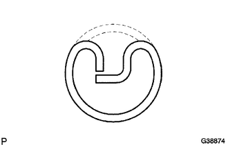
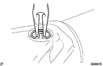
| (g) Using needle-nose pliers, install the previously selected snap ring into the groove of the yoke.
HINT: Use the same installation procedure for the universal joint spider bearing on the opposite side. |
|
(h) Temporarily install the spider and 2 universal joint spider bearings into the shaft yoke.
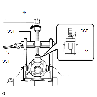
| (i) Using SST, press the universal joint spider bearing into the shaft yoke until the groove can be seen.
SST: 09336-16010 SST: 09950-40011 09951-04020 09952-04010
09953-04020 09954-04020 09955-04051 09957-04010
SST: 09950-60010 09951-00290 Text in Illustration |
*a | Spider Bearing | |
*b | Turn | |
*c | Hold |
NOTICE:
- Position SST (09336-16010) so that the cutout faces the shaft tube.
- Confirm that the universal joint spider moves smoothly while pressing in the bearing.
| |
(j) Using needle-nose pliers, install the previously selected snap ring into the groove on the shaft yoke.
HINT: Use the same installation procedure for the universal joint spider bearing on the opposite side.
2. INSTALL NO. 1 CENTER SUPPORT BEARING ASSEMBLY (a) Coat the splines of the intermediate shaft with MP grease.
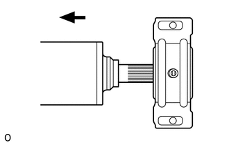 (b) Install the center support bearing to the intermediate shaft. Text in Illustration
 | Front |
| (c) Align the matchmarks on the joint yoke and intermediate shaft. Text in Illustration |
|
(d) Install the washer. (e) Clamp the yoke in a vise, and press the bearing into position by installing a new lock nut.
Torque: 128 N·m {1300 kgf·cm, 94 ft·lbf} (f) Loosen the lock nut.
(g) Tighten the lock nut again. Torque: 128 N·m {1300 kgf·cm, 94 ft·lbf}
(h) Using a chisel and hammer, stake the lock nut. 3. INSTALL PROPELLER SHAFT UNIVERSAL JOINT SPIDER BEARING
| (a) Apply MP grease to a new spider and 4 new bearings. NOTICE:
Be careful not to apply too much grease. | |
| (b) Measure dimension A between the snap ring grooves. |
|
(c) Install the 4 spider bearings to the spider journal portions, and then measure dimension B of the universal joint.
NOTICE: When measuring dimension B, fix the spider and spider bearings in a vise and hold them firmly together.
| (d) Select snap rings to make dimensions A and B the same. Hole Snap Ring Thickness: |
Color | Thickness | |
Black | 1.49 mm (0.0586 in.) | |
Copper | 1.51 mm (0.0594 in.) | |
White | 1.56 mm (0.0614 in.) | |
Blue | 1.64 mm (0.0646 in.) | |
Black | 1.52 mm (0.0598 in.) | |
Black | 1.54 mm (0.0606 in.) | |
Black | 1.62 mm (0.0638 in.) |
NOTICE:
- Use new snap rings.
- If possible, use snap rings of the same thickness for both sides.
| |
(e) Temporarily install the universal joint spider and 2 universal joint spider bearings into the propeller shaft yoke.
| (f) Using SST, press the universal joint spider bearing into the propeller shaft yoke until the groove can be seen.
SST: 09336-16010 SST: 09950-40011 09951-04020 09952-04010
09953-04020 09954-04020 09955-04051 09957-04010
SST: 09950-60010 09951-00290 Text in Illustration |
*a | Spider Bearing | |
*b | Turn | |
*c | Hold |
NOTICE: Confirm that the universal joint spider moves smoothly while pressing in the bearing. |
|
| (g) Using needle-nose pliers, install the previously selected snap ring into the groove of the yoke.
HINT: Use the same installation procedure for the universal joint spider bearing on the opposite side. |
|
(h)
Align the matchmarks on the propeller shaft yoke and universal joint
yoke, and temporarily install the spider and 2 universal joint spider
bearings into the universal joint yoke.
| (i) Using SST, press the universal joint spider bearing into the universal joint yoke until the groove can be seen.
SST: 09336-16010 SST: 09950-40011 09951-04020 09952-04010
09953-04020 09954-04020 09955-04051 09957-04010
SST: 09950-60010 09951-00290 Text in Illustration |
*a | Spider Bearing | |
*b | Turn | |
*c | Hold | |
|
(j) Using needle-nose pliers, install the previously selected snap ring into the groove on the universal joint yoke.
HINT: Use the same installation procedure for the universal joint spider bearing on the opposite side.
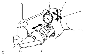
4. INSPECT PROPELLER SHAFT UNIVERSAL JOINT SPIDER BEARING
| (a) Check the spider bearings for wear and damage. | |
(b) Measure each spider bearing's axial play by turning the yoke while holding the shaft tightly.
Maximum bearing axial play: 0.05 mm (0.00197 in.) |