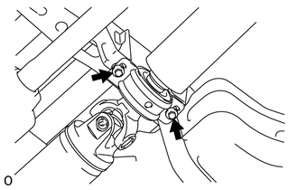
REMOVAL PROCEDURE 1. REMOVE PROPELLER WITH CENTER BEARING SHAFT ASSEMBLY  (a) Place matchmarks on the propeller shaft flange and differential flange. Text in Illustration
(b) Remove the 4 bolts and 4 nuts. Then disconnect the propeller shaft from the differential side.
(d) w/ Bearing Washer: Remove the 2 mounting bolts and 2 bearing washers from the crossmember. (e) Remove the propeller shaft.
|
Toyota Tundra Service Manual > Seat: Seat Heater Control
Components COMPONENTS ILLUSTRATION Installation INSTALLATION CAUTION / NOTICE / HINT CAUTION: Wear protective gloves. Sharp areas on the parts may injure your hands. HINT: Use the same procedure for the RH and LH sides. The procedure listed below is for the LH side. PROCEDURE 1. INSTALL SEAT HEATER ...