Toyota Tundra Service Manual: Transfer Shift Motor Control Circuit High (P17AA)

DESCRIPTION

This DTC is detected when a short to B+ is detected in the transfer shift motor drive circuit.

DTC Code

DTC Detection Condition

  1. Diagnosis Condition
  2. Malfunction Status
  3. Malfunction Time
  4. Other

Trouble Area

P17AA

  1. Ignition switch ON (when transfer shift motor is not operating)
  2. Short to B+ in the transfer shift motor drive circuit
  3. 1 second or more
  4. 1 trip detection logic
  • Wire harness and connector
  • 4 wheel drive control ECU
  • Transfer shift actuator assembly

WIRING DIAGRAM

Refer to DTCs P17A8 and P17A9 (See page ).

PROCEDURE

1.

CHECK TRANSFER SHIFT ACTUATOR ASSEMBLY (TRANSFER SHIFT MOTOR)

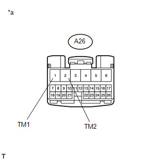
(a) Disconnect the 4 wheel drive control ECU connector.

(b) Measure the voltage according to the value(s) in the table below.

Standard Voltage:

Tester Connection

Switch Condition

Specified Condition

A26-1 (TM1) or A26-2 (TM2) - Body ground

Ignition switch ON

Below 1 V

Text in Illustration

*a

Front view of wire harness connector

(to 4 Wheel Drive Control ECU)

OK

REPLACE 4 WHEEL DRIVE CONTROL ECU

NG

2.

CHECK HARNESS AND CONNECTOR (4 WHEEL DRIVE CONTROL ECU AND TRANSFER SHIFT ACTUATOR ASSEMBLY - BODY GROUND)

(a) Disconnect the A26 4 wheel drive control ECU connector.

(b) Disconnect the D67 transfer shift actuator assembly connector.

(c) Measure the voltage according to the value(s) in the table below.

Standard Voltage:

Tester Connection

Switch Condition

Specified Condition

A26-1 (TM1) or D67-1 (TM1) - Body ground

Ignition switch ON

Below 1 V

A26-2 (TM2) or D67-2 (TM2) - Body ground

Ignition switch ON

Below 1 V

OK

REPLACE TRANSFER SHIFT ACTUATOR ASSEMBLY

NG

REPAIR OR REPLACE HARNESS OR CONNECTOR

    Transfer Shift Motor Control Circuit Circuit Open (P17A8,P17A9)

    Transfer Shift Motor Position Circuit (P17AB)

    See More:

    Toyota Tundra Service Manual > Audio And Visual System: Data Signal Circuit between Radio Receiver and Stereo Jack Adapter
    DESCRIPTION The No. 1 stereo jack adapter assembly sends the sound data signal or image data signal from a device to the radio and display receiver assembly via this circuit. WIRING DIAGRAM PROCEDURE 1. CHECK HARNESS AND CONNECTOR (RADIO AND DISPLAY RECEIVER ASSEMBLY - NO. 1 STEREO JACK ADAPTER ASSE ...

    Toyota Tundra Owners Manual

    Toyota Tundra Service Manual

    © 2026 Copyright www.ttundra.com
    0.0098