REMOVAL PROCEDURE 1. PRECAUTION NOTICE: After turning the ignition switch off, waiting time may be required before disconnecting the cable from the battery terminal. Therefore, make sure to read the disconnecting the cable from the battery terminal notice before proceeding with work. Click here 2. DISCONNECT CABLE FROM NEGATIVE BATTERY TERMINAL CAUTION: Wait at least 90 seconds after disconnecting the cable from the negative (-) battery terminal to disable the SRS system. NOTICE: When disconnecting the cable, some systems need to be initialized after the cable is reconnected. Click here 3. REMOVE FRONT DOOR SCUFF PLATE RH (a) for Double Cab: HINT: Use the same procedure described for the LH side. Click here (b) for CrewMax: HINT: Use the same procedure described for the LH side. Click here 4. REMOVE COWL SIDE TRIM BOARD RH (a) for Double Cab: HINT: Use the same procedure described for the LH side. Click here
(b) for CrewMax: HINT: Use the same procedure described for Double Cab. 5. REMOVE NO. 2 INSTRUMENT PANEL UNDER COVER SUB-ASSEMBLY (a) for Column Shift Type: Click here (b) for Floor Shift Type: HINT: Use the same procedure described for Column Shift Type. 6. REMOVE INSTRUMENT SIDE PANEL RH (a) for Column Shift Type: Click here
(b) for Floor Shift Type: HINT: Use the same procedure described for Column Shift Type. 7. REMOVE LOWER INSTRUMENT PANEL (a) for Column Shift Type: Click here (b) for Floor Shift Type: HINT: Use the same procedure described for Column Shift Type. 8. REMOVE LOWER NO. 2 INSTRUMENT PANEL AIRBAG ASSEMBLY Click here
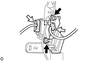
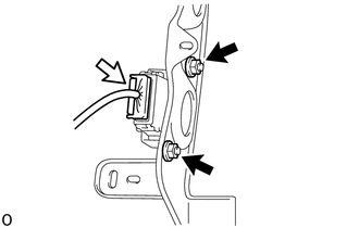
9. REMOVE LOWER INSTRUMENT PANEL FINISH PANEL SUB-ASSEMBLY RH (a) for Column Shift Type: Click here (b) for Floor Shift Type: HINT: Use the same procedure described for Column Shift Type. 10. REMOVE NETWORK GATEWAY ECU
|
Toyota Tundra Service Manual > Lighting System: Turn Signal Switch Circuit
DESCRIPTION The combination meter assembly receives the turn signal switch information and controls the turn signal lights. WIRING DIAGRAM CAUTION / NOTICE / HINT NOTICE: When replacing the combination meter assembly, always replace it with a new one. If a combination meter assembly which was instal ...