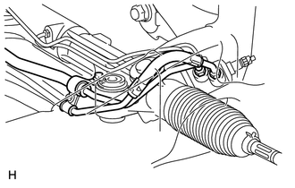
INSTALLATION PROCEDURE 1. INSTALL POWER STEERING GEAR ASSEMBLY (a) Insert the power steering gear assembly into the vehicle in the order shown in the illustration. 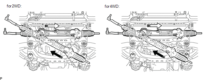
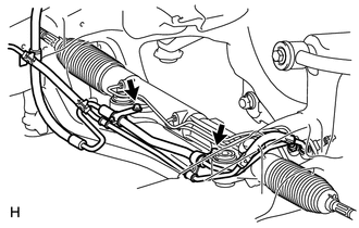
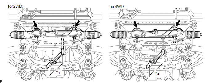
(f) Install the power steering gear with the 2 bolts and 2 nuts. SST: 09961-01270 Torque: Specified tightening torque : 120 N·m {1224 kgf·cm, 89 ft·lbf} HINT:
2. INSTALL FRONT DIFFERENTIAL CARRIER ASSEMBLY Click here
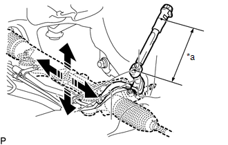
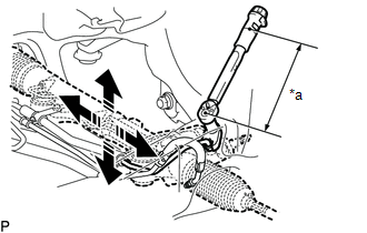
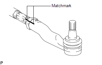
3. INSTALL TIE ROD END SUB-ASSEMBLY LH (a) Align the matchmarks of the tie rod and rack end and temporarily install the tie rod with the lock nut.
4. CONNECT TIE ROD END SUB-ASSEMBLY LH (a) Connect the tie rod end LH to the steering knuckle with the nut. Torque: 69 N·m {704 kgf·cm, 51 ft·lbf} (b) Install a new cotter pin. HINT: Further tighten the nut up to 60° if the holes for the cotter pin are not aligned. 5. CONNECT TIE ROD END SUB-ASSEMBLY RH HINT: Use the same procedures described for the LH side. 6. CONNECT NO. 2 STEERING INTERMEDIATE SHAFT SUB-ASSEMBLY 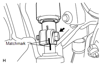 (a) Align the matchmarks on the No. 2 steering intermediate shaft and power steering gear. (b) Install the bolt. Torque: 35 N·m {360 kgf·cm, 26 ft·lbf} 7. INSTALL NO. 1 ENGINE UNDER COVER Click here
8. INSTALL FRONT WHEEL Torque: for Aluminum Wheel : 131 N·m {1336 kgf·cm, 97 ft·lbf} for Steel Wheel : 209 N·m {2131 kgf·cm, 154 ft·lbf} 9. BLEED POWER STEERING FLUID (for 1UR-FE) 10. BLEED POWER STEERING FLUID (for 3UR-FE, 3UR-FBE) 11. CHECK POWER STEERING FLUID LEVEL (for 1UR-FE) 12. CHECK POWER STEERING FLUID LEVEL (for 3UR-FE, 3UR-FBE) 13. INSPECT FOR POWER STEERING FLUID LEAK 14. PLACE FRONT WHEELS FACING STRAIGHT AHEAD HINT: Perform this procedure with the front of the vehicle jacked up. 15. ADJUST FRONT WHEEL ALIGNMENT (a) Adjust the front wheel alignment (See page
|
Toyota Tundra Service Manual > Power Window Control System(w/ Jam Protection Function): System Description
SYSTEM DESCRIPTION 1. POWER WINDOW CONTROL SYSTEM DESCRIPTION The power window control system controls the power window UP/DOWN function using the power window regulator motor. The main controls of this system are the master switch, which is built into the driver side door, and the power window regu ...