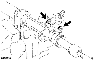
REASSEMBLY CAUTION / NOTICE / HINT NOTICE: When installing, coat the parts indicated by the arrows with power steering fluid (See page
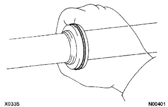
PROCEDURE 1. INSTALL RACK STEERING PISTON RING
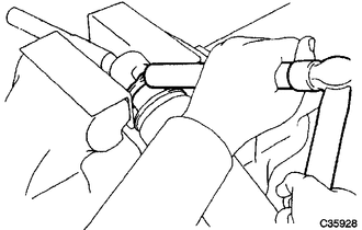
(b) Expand a new piston ring with your fingers. NOTICE: Be careful not to over expand the rack steering piston ring. (c) Coat a new piston ring with power steering fluid.
2. INSTALL POWER STEERING CYLINDER TUBE OIL SEAL (a) Coat a new cylinder tube oil seal lip with power steering fluid.
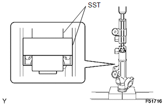
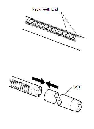
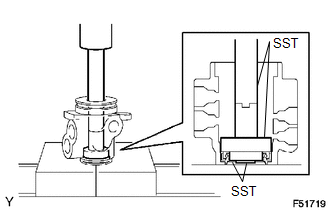
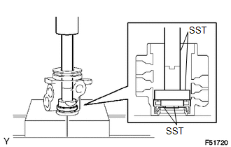
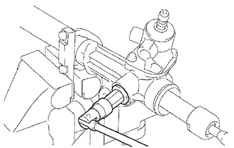
3. INSTALL POWER STEERING RACK
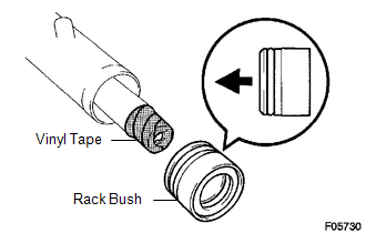
(b) Coat SST with power steering fluid. (c) Install the power steering rack into the rack housing. (d) Remove SST. 4. INSTALL POWER STEERING RACK BUSH
(b) Coat a new O-ring with power steering fluid and install it onto the rack bush.
(d) Install the rack bush onto the power steering rack. 5. INSTALL CYLINDER END STOPPER
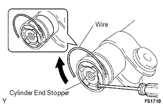
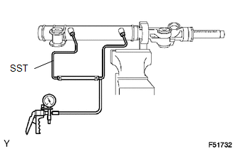
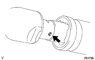
(b) Install a new wire into the cylinder end stopper. (c) Using a screwdriver, turn the cylinder end stopper clockwise by 400 to 500°. 6. AIR TIGHT TEST
(b) Apply a vacuum of 53 kPa (400 mmHg, 15.75 in.Hg) for about 30 seconds. (c) Check that there is no change in the vacuum. If there is any change in the vacuum, check whether the oil seals are installed correctly. 7. INSTALL POWER STEERING CONTROL VALVE UPPER OIL SEAL (a) Coat the control valve upper bearing and a new control valve upper oil seal with power steering fluid.
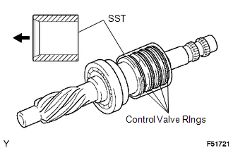
8. INSTALL POWER STEERING CONTROL VALVE ASSEMBLY 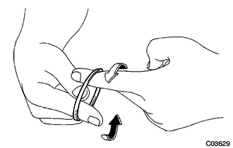 (a) Expand 4 new control valve rings with your fingers. NOTICE: Be careful not to over expand the control valve rings. (b) Coat the 4 control valve rings with power steering fluid. (c) Install the 4 control valve rings onto the control valve, and position them with your fingers.
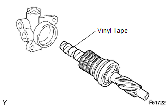
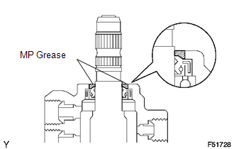
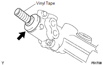
(f) Coat the control valve upper oil seal lip with power steering fluid. (g) Install the control valve onto the control valve housing. NOTICE: Be careful not to damage the control valve ring and control valve upper oil seal lip. (h) Apply grease to the needle roller bearing. (i) Install a new O-ring onto the control valve housing. (j) Wind vinyl tape around the serrated portion of the control valve.
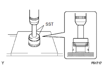
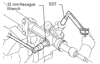
9. INSTALL STEERING GEAR RACK GUIDE (a) Install the rack guide. (b) Install the rack guide spring. (c) Apply adhesive to 2 or 3 threads of the rack guide spring cap. Adhesive: Toyota Genuine Adhesive 1344, Three Bond 1344 or equivalent (d) Provisionally install the rack guide spring cap. 10. ADJUST TOTAL PRELOAD (a) To prevent the steering rack teeth from damaging the oil seal lip, provisionally install the RH and LH steering rack end. (b) Using 32 mm hexagon wrench, torque the rack guide spring cap. Torque: 30 N·m {306 kgf·cm, 22 ft·lbf}
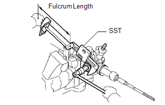
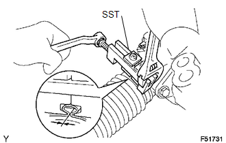
(e) Using SST, loosen the rack guide spring cap until the rack guide spring ceases to function.
(g) Apply adhesive to 2 or 3 threads of the rack guide spring cap nut. Adhesive: Toyota Genuine Adhesive 1344, Three Bond 1344 or equivalent (h) Provisionally install the rack guide spring cap nut.
(j) Recheck the total preload. Preload (turning): 1.9 to 2.7 N*m (19.4 to 27.5 kgf*cm, 16.8 to 23.9 in.*lbf) (k) Remove the RH and LH steering rack ends.
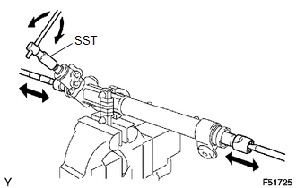
(n) Install the dust cover onto the control valve housing. 11. INSTALL STEERING RACK END SUB-ASSEMBLY
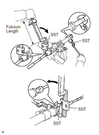
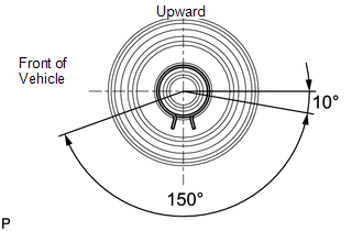
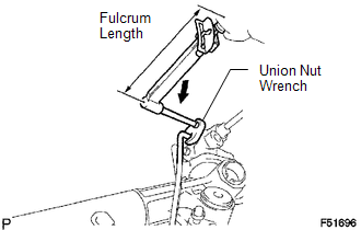
(b) Using 2 SST, install the 2 steering rack ends. SST: 09922-10010 Torque: without SST : 195 N·m {1988 kgf·cm, 144 ft·lbf} with SST : 142 N·m {1448 kgf·cm, 105 ft·lbf} NOTICE: Turn SST 09922-10010 in the direction shown in the illustration. HINT:
12. INSPECT STEERING RACK END SUB-ASSEMBLY
13. INSTALL STEERING RACK BOOT NO. 1 14. INSTALL STEERING RACK BOOT NO. 2 15. INSTALL STEERING RACK BOOT NO. 1 CLAMP
16. INSTALL STEERING RACK BOOT NO. 2 CLAMP HINT: The installation procedure for the No. 2 side is the same as that for the No. 1 side. 17. INSTALL STEERING RACK BOOT CLIP
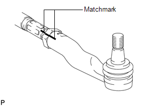
18. INSTALL TIE ROD END SUB-ASSEMBLY LH (a) Align the matchmarks of the tie rod and rack end and temporarily install the tie rod with the lock nut.
19. INSTALL TIE ROD END SUB-ASSEMBLY RH HINT: The installation procedure for the RH side is the same as that for the LH side. 20. INSTALL STEERING TURN PRESSURE TUBE (a) Coat 4 new O-rings with power steering fluid and install them onto the pressure tubes.
|
Toyota Tundra Service Manual > Steering Angle Sensor: Removal
REMOVAL PROCEDURE 1. PRECAUTION NOTICE: After turning the ignition switch off, waiting time may be required before disconnecting the cable from the battery terminal. Therefore, make sure to read the disconnecting the cable from the battery terminal notice before proceeding with work (See page ). 2. ...

 ).
).