REMOVAL PROCEDURE 1. PLACE FRONT WHEELS FACING STRAIGHT AHEAD 2. REMOVE FRONT WHEELS 3. DISCONNECT NO. 2 STEERING INTERMEDIATE SHAFT SUB-ASSEMBLY
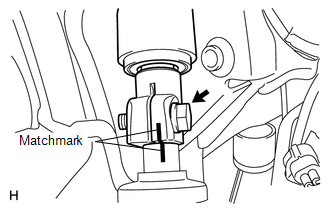
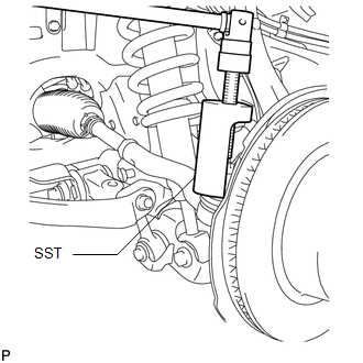
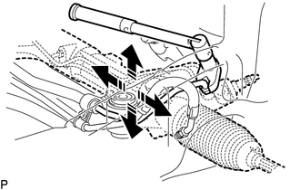
(b) Remove the bolt and disconnect the No. 2 steering intermediate shaft from the power steering gear. 4. DISCONNECT TIE ROD END SUB-ASSEMBLY LH (a) Remove the cotter pin and nut.
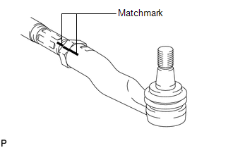
5. DISCONNECT TIE ROD END SUB-ASSEMBLY RH HINT: Use the same procedures described for the LH side. 6. REMOVE TIE ROD END SUB-ASSEMBLY LH HINT: Only remove the tie rod end sub-assembly LH. The tie rod end sub-assembly RH does not need to be removed.
(b) Remove the tie rod assembly LH and lock nut. 7. REMOVE NO. 1 ENGINE UNDER COVER Click here 8. REMOVE FRONT DIFFERENTIAL CARRIER ASSEMBLY Click here
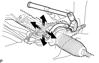
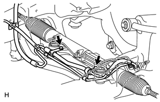
9. REMOVE POWER STEERING GEAR ASSEMBLY (a) Remove the 2 bolts, 2 nuts and power steering gear. 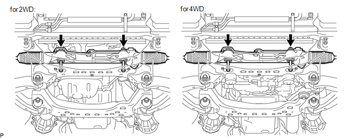
(e) Pull the power steering gear assembly out of the vehicle in the order shown in the illustration. 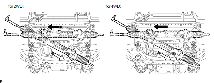
|
Toyota Tundra Service Manual > Center Power Outlet Socket(for Floor Shift Type): Installation
INSTALLATION PROCEDURE 1. INSTALL POWER OUTLET SOCKET COVER (for Double Cab) (a) Attach the 2 claws to install the power outlet socket cover. 2. INSTALL POWER OUTLET SOCKET ASSEMBLY (for Double Cab) (a) Attach the claw to install the power outlet socket assembly. 3. INSTALL REAR CONSOLE END PANEL SU ...