REASSEMBLY PROCEDURE 1. INSTALL NO. 1 MONOLITHIC CONVERTER PROTECTOR (for Bank 2) (a) Install the 4 No. 1 converter protector stays to the front exhaust pipe assembly. (b) Install the lower No. 1 monolithic converter protector and upper No. 1 monolithic converter protector with the 4 bolts and 4 nuts. Torque: 11 N·m {107 kgf·cm, 8 ft·lbf} HINT: Install the No. 1 monolithic converter protector within the angle range specified in the illustration. 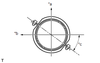 Text in Illustration Text in Illustration
2. INSTALL MONOLITHIC CONVERTER PROTECTOR (for Bank 2) (a) Install the 2 No. 1 converter protector stays and 2 No. 2 converter protector stays to the front exhaust pipe assembly. (b) Install the lower monolithic converter protector and upper monolithic converter protector with the 4 bolts and 4 nuts. Torque: 11 N·m {107 kgf·cm, 8 ft·lbf} HINT: Install the monolithic converter protector within the angle range specified in the illustration. 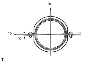 Text in Illustration Text in Illustration
3. INSTALL NO. 1 MONOLITHIC CONVERTER PROTECTOR (for Bank 1) (a) Install the 4 No. 1 converter protector stays to the front No. 2 exhaust pipe assembly. (b) Install the lower No. 1 monolithic converter protector and upper No. 1 monolithic converter protector with the 4 bolts and 4 nuts. Torque: 11 N·m {107 kgf·cm, 8 ft·lbf} HINT: Install the No. 1 monolithic converter protector within the angle range specified in the illustration. 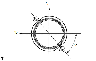 Text in Illustration Text in Illustration
4. INSTALL MONOLITHIC CONVERTER PROTECTOR (for Bank 1) (a) Install the 2 No. 1 converter protector stays and 2 No. 2 converter protector stays to the front No. 2 exhaust pipe assembly. (b) Install the lower monolithic converter protector and upper monolithic converter protector with the 4 bolts and 4 nuts. Torque: 11 N·m {107 kgf·cm, 8 ft·lbf} HINT: Install the monolithic converter protector within the angle range specified in the illustration. 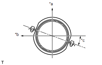 Text in Illustration Text in Illustration
|
Toyota Tundra Service Manual > Power Tilt And Power Telescopic Steering Column System: Tilt and Telescopic Manual Switch Circuit Malfunction (B2603)
DESCRIPTION Different voltage values are sent to the multiplex tilt and telescopic ECU by operating the tilt and telescopic switch (headlight dimmer switch assembly). The multiplex tilt and telescopic ECU then judges which motor and in which direction that motor should operate based on the voltage v ...


