Toyota Tundra Service Manual: Components

COMPONENTS

ILLUSTRATION
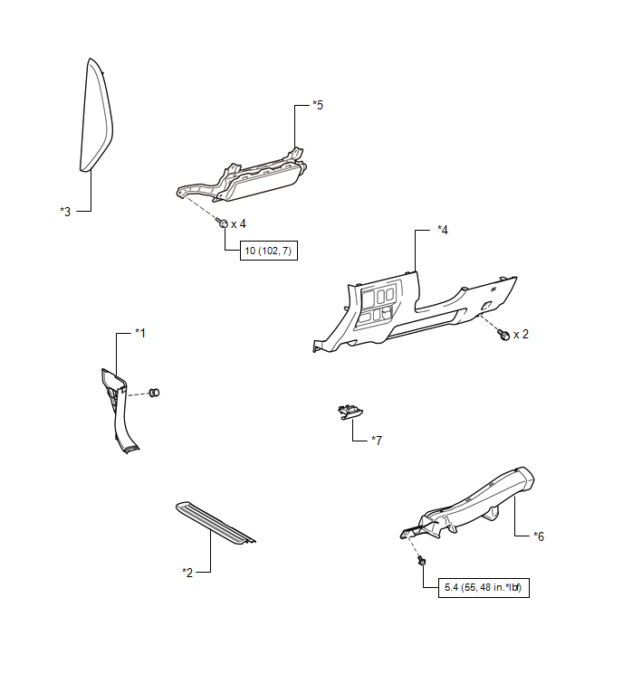
*1

COWL SIDE TRIM BOARD LH

*2

FRONT DOOR SCUFF PLATE LH

*3

INSTRUMENT SIDE PANEL LH

*4

LOWER INSTRUMENT PANEL FINISH PANEL SUB-ASSEMBLY LH

*5

LOWER NO. 1 INSTRUMENT PANEL AIRBAG ASSEMBLY

*6

NO. 3 AIR DUCT SUB-ASSEMBLY

*7

HOOD LOCK CONTROL LEVER

-

-

N*m (kgf*cm, ft.*lbf): Specified torque

-

-

ILLUSTRATION

*1

LOWER STEERING COLUMN COVER

*2

MULTIPLEX TILT AND TELESCOPIC ECU

*3

UPPER STEERING COLUMN COVER

-

-

    Multiplex Tilt And Telescopic Ecu(for Power Tilt And Power Telescopic Steering Column)

    Installation

    See More:

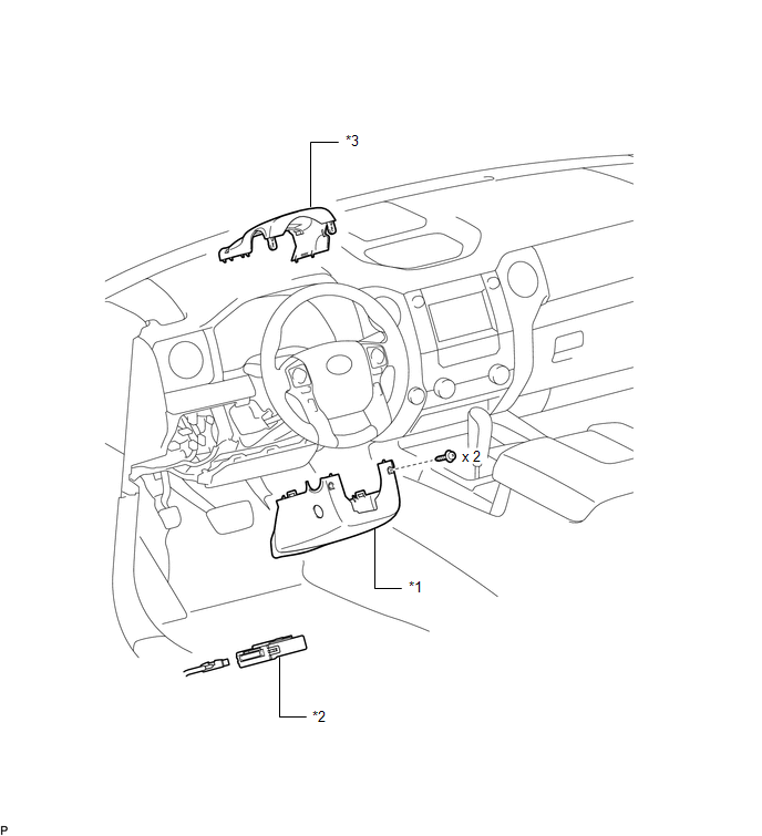
    Toyota Tundra Service Manual > Sfi System: Camshaft Position Sensor "A" (Bank 1 Sensor 2) (P1340,P1342,P1343)
    DESCRIPTION The camshaft position sensor (G signal) consists of a magnet and MRE (Magnetoresistive Element). The camshaft drive gear (LH) has 3 teeth on its outer circumference. When the camshaft gear rotates, the air gap between the protrusion on the gear and the MRE changes. The change affects the ...

    Toyota Tundra Owners Manual

    Toyota Tundra Service Manual

    © 2026 Copyright www.ttundra.com
    0.0127