INSTALLATION PROCEDURE 1. INSTALL NO. 1 COOLER THERMISTOR NOTICE: If reusing the evaporator, do not insert the No. 1 cooler thermistor into a location where the No. 1 cooler thermistor was previously inserted. Insert the No. 1 cooler thermistor within range C shown in the illustration. 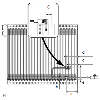
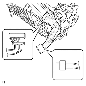
(a) Install the No. 1 cooler thermistor to the No. 1 cooler evaporator sub-assembly as shown in the illustration.
2. INSTALL NO. 1 COOLER EVAPORATOR SUB-ASSEMBLY (a) Install the No. 1 cooler evaporator sub-assembly to the blower assembly. 3. INSTALL BLOWER ASSEMBLY (a) Attach the 3 claws to install the blower assembly. (b) Install the 6 screws.
(d) Attach the 3 claws to install the heater clamp. 4. INSTALL AIR CONDITIONING AMPLIFIER ASSEMBLY
5. INSTALL NO. 3 AIR DUCT SUB-ASSEMBLY
6. INSTALL AIR CONDITIONING UNIT (See page |
Toyota Tundra Service Manual > 1ur-fe Fuel: Fuel Sender Gauge Assembly
ComponentsCOMPONENTS ILLUSTRATION InspectionINSPECTION PROCEDURE 1. INSPECT FUEL SENDER GAUGE ASSEMBLY (a) Check that the float moves smoothly between F and E. (b) Measure the resistance according to the value(s) in the table below. Standard Resistance: Tester Connection Condition Specified Conditi ...