REASSEMBLY PROCEDURE 1. INSTALL STEERING COLUMN BRACKET SPACER 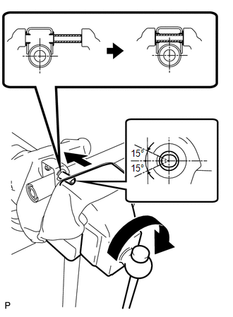 (a) Fix the steering column in a vise between aluminum plates or a cloth. Then install the steering column bracket spacer to the steering column. NOTICE:
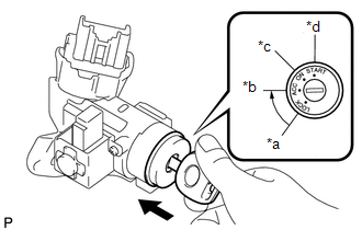
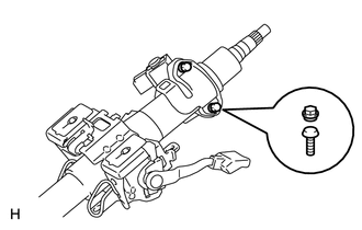
2. INSTALL IGNITION SWITCH ASSEMBLY 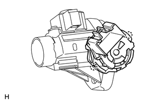 (a) Attach the 2 claws to install the ignition switch to the switch bracket. 3. INSTALL KEY INTERLOCK SOLENOID 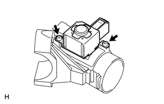 (a) Install the key interlock solenoid to the switch bracket with the 2 screws. 4. INSTALL UNLOCK WARNING SWITCH ASSEMBLY 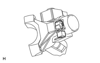 (a) Attach the 2 claws to install the unlock warning switch to the switch bracket. 5. INSTALL IGNITION SWITCH LOCK CYLINDER (a) Check that the ignition switch lock cylinder is in the ACC position.
(c) Check that the ignition switch lock cylinder assembly is securely installed. 6. INSPECT STEERING LOCK OPERATION 7. INSTALL UPPER STEERING COLUMN WITH SWITCH BRACKET ASSEMBLY (a) Temporarily install the upper steering column with switch bracket and steering lock bracket with 2 new tapered-head bolts.
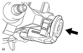
8. INSTALL TRANSPONDER KEY AMPLIFIER (w/ Engine Immobiliser System) (a) Align the transponder key amplifier with the installation position of the switch bracket with the amplifier inclined.
9. INSTALL KEY CYLINDER LIGHT ASSEMBLY (w/o Engine Immobiliser System) (a) Align the key cylinder light with the installation position of the switch bracket with the key cylinder light inclined.
|
Toyota Tundra Service Manual > Steering System: Precaution
PRECAUTION 1. HANDLING PRECAUTIONS FOR STEERING SYSTEM (a) The vehicle is equipped with an SRS (Supplemental Restraint System) such as airbags. Failure to carry out service operations in the correct sequence could cause the SRS to unexpectedly deploy during servicing. This may cause a serious accide ...