DESCRIPTION The ambient temperature sensor is installed in front of the condenser to detect the ambient temperature which is used to control the air conditioner "AUTO" mode. This sensor is connected to the air conditioning amplifier and detects fluctuations in the ambient temperature. This data is used for controlling the cabin temperature. The sensor sends a signal to the air conditioning amplifier. The resistance of the ambient temperature sensor changes in accordance with the ambient temperature. As the temperature decreases, the resistance increases. As the temperature increases, the resistance decreases. The air conditioning amplifier applies voltage (5 V) to the ambient temperature sensor and reads voltage changes as the resistance of the ambient temperature sensor changes.
WIRING DIAGRAM 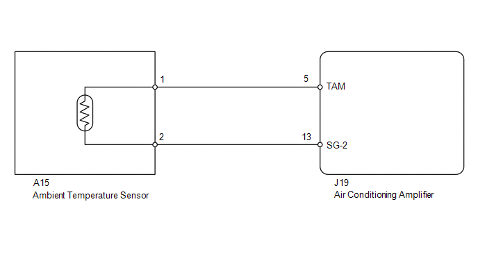
PROCEDURE
(a) Use the Data List to check if the ambient temperature sensor is functioning properly. Air Conditioner
OK: The display is as specified in the normal condition. Result
(a) Remove the ambient temperature sensor (see page
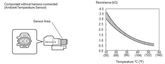
(b) Measure the resistance according to the value(s) in the table below. Standard resistance:
NOTICE:
HINT: As the temperature increases, the resistance decreases (see the graph).
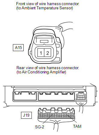
(a) Disconnect the A15 sensor connector. (b) Disconnect the J19 air conditioning amplifier connector. (c) Measure the resistance according to the value(s) in the table below. Standard resistance:
|
Toyota Tundra Service Manual > Vehicle Stability Control System: VSC does not Operate or VSC does not Operate Correctly
DESCRIPTION When TRAC or VSC is operating, the skid control ECU (brake actuator assembly) blinks the slip indicator light to inform the driver that slippage occurred. When a communication malfunction with the ECM is detected, TRAC and VSC are disabled. Also, TRAC and VSC are disabled when a DTC is s ...


