DESCRIPTION The room temperature sensor is installed in the instrument panel to detect the room temperature and control the heater and air conditioner "AUTO" mode. The resistance of the room temperature sensor changes in accordance with the room temperature. As the temperature decreases, the resistance increases. As the temperature increases, the resistance decreases. The air conditioning amplifier applies voltage (5 V) to the room temperature sensor and reads voltage changes as the resistance of the room temperature sensor changes. This sensor also sends the appropriate signals to the air conditioning amplifier.
WIRING DIAGRAM 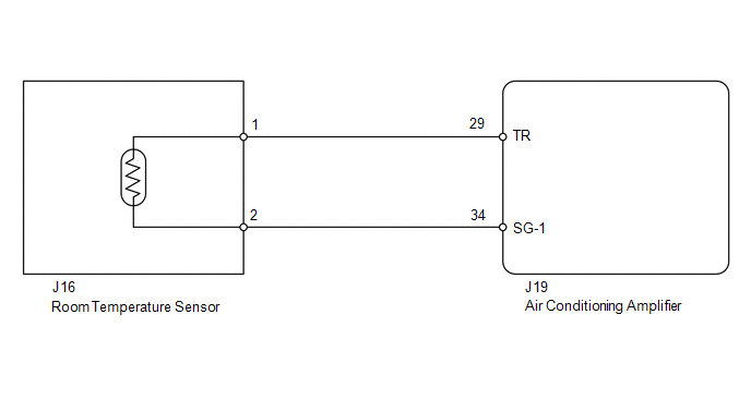
PROCEDURE
(a) Use the Data List to check if the room temperature sensor is functioning properly. Air Conditioner
OK: The display is as specified in the normal condition. Result
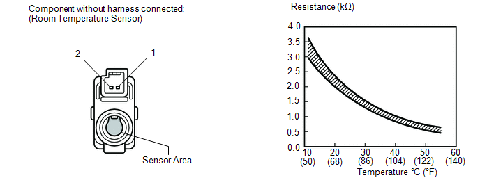
(a) Remove the room temperature sensor (see page
(b) Measure the resistance according to the value(s) in the table below. Standard resistance:
NOTICE:
HINT: As the temperature increases, the resistance decreases (see the graph).
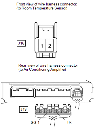
(a) Disconnect the J16 sensor connector. (b) Disconnect the J19 air conditioning amplifier connector. (c) Measure the resistance according to the value(s) in the table below. Standard resistance:
|
Toyota Tundra Owners Manual > Driving procedures: Turn signal lever
Operating instructions Right turn Lane change to the right (move the lever partway and release it) The right hand signals will flash 3 times. Lane change to the left (move the lever partway and release it) The left hand signals will flash 3 times. Left turn ■Turn signals can be operated when The e ...


