DESCRIPTION This circuit provides power to operate the air conditioning amplifier. WIRING DIAGRAM 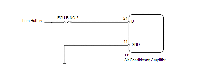
PROCEDURE
(a) Remove the ECU-B NO.2 fuse from the driver side junction block. (b) Measure the resistance according to the value(s) in the table below. Standard resistance:
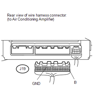
(a) Disconnect the J19 air conditioning amplifier connector. (b) Measure the resistance and voltage according to the value(s) in the table below. Standard resistance:
Standard voltage:
|
Toyota Tundra Service Manual > Audio / Video: Floor Speaker(for Crewmax)
ComponentsCOMPONENTS ILLUSTRATION InspectionINSPECTION PROCEDURE 1. INSPECT NO. 1 BOX SPEAKER ASSEMBLY (a) Measure the resistance according to the value(s) in the table below. Standard resistance: Tester Connection Condition Specified Condition 1 - 2 Always 1.6 to 2.4 Ω If the result is not as spe ...


