DESCRIPTION This DTC is stored when a malfunction occurs in the speakers. |
DTC Code | DTC Detection Condition |
Trouble Area | | B15C3 |
A short is detected in the speaker output circuit. |
- Speakers
- Harness or connector
- Stereo component amplifier assembly
- Radio and display receiver assembly
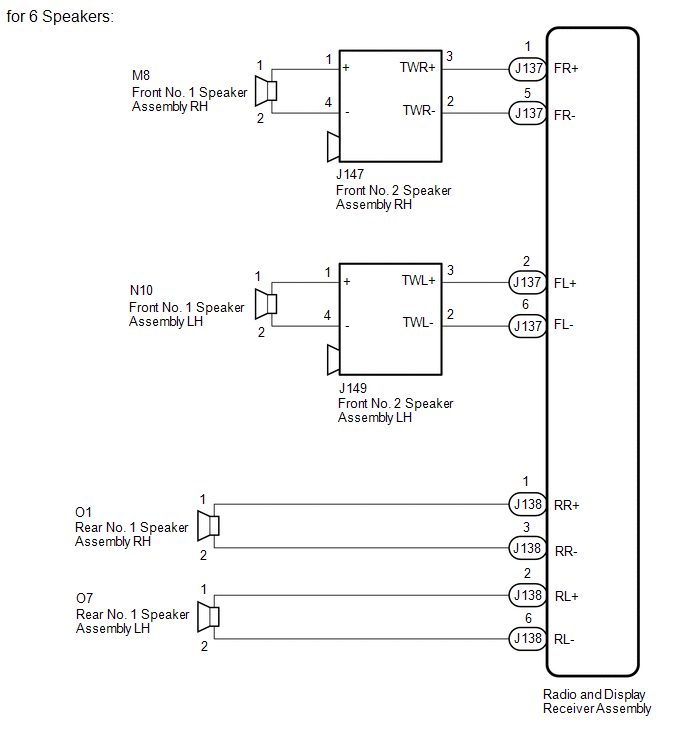
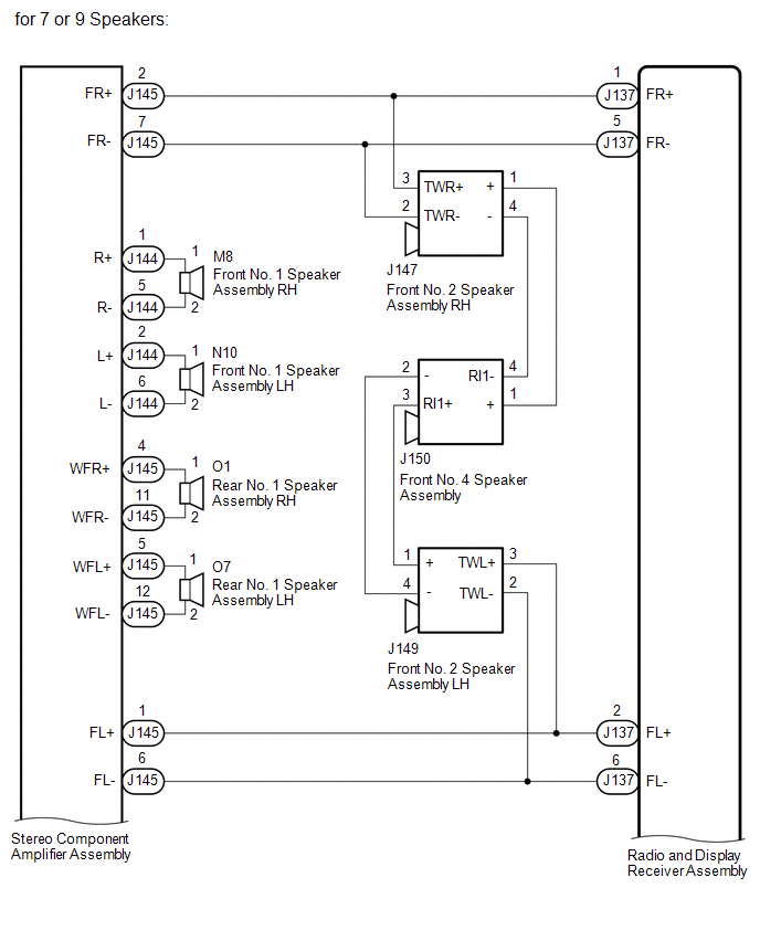
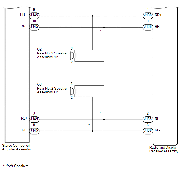
| WIRING DIAGRAM
 PROCEDURE
(a) Disconnect the J137 and J138 radio and display receiver assembly connectors.
(b) Clear the DTCs (See page  ). ). (c) Check for DTCs (See page
). OK: No DTCs are output. Result |
Result | Proceed to | |
OK | A | |
NG (for Column Shift Type) |
B | | NG (for Floor Shift Type) |
C |
| B |
 | REPLACE RADIO AND DISPLAY RECEIVER ASSEMBLY |
| C |
| REPLACE RADIO AND DISPLAY RECEIVER ASSEMBLY |
|
A |
 | |
| 2. |
CHECK VEHICLE CONDITION | (a) Check the vehicle condition. Result |
Result | Proceed to | |
for 6 Speakers | A | |
for 7 or 9 Speakers | B |
| B |
| GO TO STEP 7 |
|
A | |
| |
| 3. |
CHECK HARNESS AND CONNECTOR (SPEAKER CIRCUIT) |
- *1: for RH Side
- *2: for LH Side
(a) Disconnect the J137 and J138 radio and display receiver assembly connectors.
(b) Disconnect the M8*1 and/or N10*2 front No. 1 speaker assembly connector.
(c) Disconnect the J147*1 and/or J149*2 front No. 2 speaker assembly connector.
(d) Disconnect the O1*1 and/or O7*2 rear No. 1 speaker assembly connector.
(e) Measure the resistance according to the value(s) in the table below.
Standard Resistance: for RH side |
Tester Connection | Condition |
Specified Condition | |
J137-1 (FR+) - J147-3 (TWR+) |
Always | Below 1 Ω | |
J137-5 (FR-) - J147-2 (TWR-) |
Always | Below 1 Ω | |
J147-1 (+) - M8-1 | Always |
Below 1 Ω | |
J147-4 (-) - M8-2 | Always |
Below 1 Ω | |
J138-1 (RR+) - O1-1 | Always |
Below 1 Ω | |
J138-3 (RR-) - O1-2 | Always |
Below 1 Ω | |
J137-1 (FR+) - Body ground |
Always | 10 kΩ or higher | |
J137-5 (FR-) - Body ground |
Always | 10 kΩ or higher | |
J147-1 (+) - Body ground |
Always | 10 kΩ or higher | |
J147-4 (-) - Body ground |
Always | 10 kΩ or higher | |
J138-1 (RR+) - Body ground |
Always | 10 kΩ or higher | |
J138-3 (RR-) - Body ground |
Always | 10 kΩ or higher |
for LH side |
Tester Connection | Condition |
Specified Condition | |
J137-2 (FL+) - J149-3 (TWL+) |
Always | Below 1 Ω | |
J137-6 (FL-) - J149-2 (TWL-) |
Always | Below 1 Ω | |
J149-1 (+) - N10-1 | Always |
Below 1 Ω | |
J149-4 (-) - N10-2 | Always |
Below 1 Ω | |
J138-2 (RL+) - O7-1 | Always |
Below 1 Ω | |
J138-6 (RL-) - O7-2 | Always |
Below 1 Ω | |
J137-2 (FL+) - Body ground |
Always | 10 kΩ or higher | |
J137-6 (FL-) - Body ground |
Always | 10 kΩ or higher | |
J149-1 (+) - Body ground |
Always | 10 kΩ or higher | |
J149-4 (-) - Body ground |
Always | 10 kΩ or higher | |
J138-2 (RL+) - Body ground |
Always | 10 kΩ or higher | |
J138-6 (RL-) - Body ground |
Always | 10 kΩ or higher |
| NG |
| REPAIR OR REPLACE HARNESS OR CONNECTOR |
|
OK | |
| |
| 4. |
INSPECT FRONT NO. 1 SPEAKER ASSEMBLY | (a) Remove the front No. 1 speaker assembly (See page
). (b) Inspect the front No. 1 speaker assembly (See page
).
| NG | |
REPLACE FRONT NO. 1 SPEAKER ASSEMBLY |
|
OK | |
| |
| 5. |
CHECK FRONT NO. 2 SPEAKER ASSEMBLY | (a) Replace the front No. 2 speaker assembly with a known good one (See page
). (b) Check that the malfunction disappears.
NOTICE:
- Connect all the connectors to the front No. 2 speaker assemblies that were disconnected.
- Connect all the connectors to the front No. 2 speaker assemblies that were disconnected.
- Perform the above inspection on both LH and RH sides.
OK: Malfunction disappears.
| OK |
| END (FRONT NO. 2 SPEAKER ASSEMBLY IS DEFECTIVE) |
|
NG | |
| |
| 6. |
INSPECT REAR NO. 1 SPEAKER ASSEMBLY | (a) Remove the rear No. 1 speaker assembly (See page
). (b) Inspect the rear No. 1 speaker assembly (See page
). Result |
Result | Proceed to | |
OK (for Column Shift Type) |
A | | OK (for Floor Shift Type) |
B | | NG |
C |
| A |
| REPLACE RADIO AND DISPLAY RECEIVER ASSEMBLY |
| B |
| REPLACE RADIO AND DISPLAY RECEIVER ASSEMBLY |
| C |
| REPLACE REAR NO. 1 SPEAKER ASSEMBLY |
| 7. |
CHECK HARNESS AND CONNECTOR (SPEAKER CIRCUIT) |
- *1: for RH Side
- *2: for LH Side
- *3: for 9 Speakers
(a) Disconnect the J137 and J138 radio and display receiver assembly connectors.
(b) Disconnect the M8*1 and/or N10*2 front No. 1 speaker assembly connector.
(c) Disconnect the J147*1 and/or J149*2 front No. 2 speaker assembly connector.
(d) Disconnect the J150 front No. 4 speaker assembly connector. (e) Disconnect the O1*1 and/or O7*2 rear No. 1 speaker assembly connector.
(f) Disconnect the O2*1 and/or O8*2 rear No. 2 speaker assembly connector*3.
(g) Disconnect the J144 and J145 stereo component amplifier assembly connectors.
(h) Measure the resistance according to the value(s) in the table below.
Standard Resistance: for RH side |
Tester Connection | Condition |
Specified Condition | |
J137-1 (FR+) - J145-2 (FR+) |
Always | Below 1 Ω | |
J137-5 (FR-) - J145-7 (FR-) |
Always | Below 1 Ω | |
J137-1 (FR+) - J147-3 (TWR+) |
Always | Below 1 Ω | |
J137-5 (FR-) - J147-2 (TWR-) |
Always | Below 1 Ω | |
J147-1 (+) - J150-1 (+) |
Always | Below 1 Ω | |
J147-4 (-) - J150-4 (RI1-) |
Always | Below 1 Ω | |
J144-1 (R+) - M8-1 | Always |
Below 1 Ω | |
J144-5 (R-) - M8-2 | Always |
Below 1 Ω | |
J138-1 (RR+) - J145-9 (RR+) |
Always | Below 1 Ω | |
J138-3 (RR-) - J145-10 (RR-) |
Always | Below 1 Ω | |
J138-1 (RR+) - O2-3* |
Always | Below 1 Ω | |
J138-3 (RR-) - O2-2* |
Always | Below 1 Ω | |
J145-4 (WFR+) - O1-1 |
Always | Below 1 Ω | |
J145-11 (WFR-) - O1-2 |
Always | Below 1 Ω | |
J137-1 (FR+) - Body ground |
Always | 10 kΩ or higher | |
J137-5 (FR-) - Body ground |
Always | 10 kΩ or higher | |
J147-1 (+) - Body ground |
Always | 10 kΩ or higher | |
J147-4 (-) - Body ground |
Always | 10 kΩ or higher | |
J144-1 (R+) - Body ground |
Always | 10 kΩ or higher | |
J144-5 (R-) - Body ground |
Always | 10 kΩ or higher | |
J138-1 (RR+) - Body ground |
Always | 10 kΩ or higher | |
J138-3 (RR-) - Body ground |
Always | 10 kΩ or higher | |
J145-4 (WFR+) - Body ground |
Always | 10 kΩ or higher | |
J145-11 (WFR-) - Body ground |
Always | 10 kΩ or higher |
for LH side |
Tester Connection | Condition |
Specified Condition | |
J137-2 (FL+) - J145-1 (FL+) |
Always | Below 1 Ω | |
J137-6 (FL-) - J145-6 (FL-) |
Always | Below 1 Ω | |
J137-2 (FL+) - J149-3 (TWL+) |
Always | Below 1 Ω | |
J137-6 (FL-) - J149-2 (TWL-) |
Always | Below 1 Ω | |
J149-1 (+) - J150-3 (RI1+) |
Always | Below 1 Ω | |
J149-4 (-) - J150-2 (-) |
Always | Below 1 Ω | |
J144-2 (L+) - N10-1 | Always |
Below 1 Ω | |
J144-6 (L-) - N10-2 | Always |
Below 1 Ω | |
J138-2 (RL+) - J145-3 (RL+) |
Always | Below 1 Ω | |
J138-6 (RL-) - J145-8 (RL-) |
Always | Below 1 Ω | |
J138-2 (RL+) - O8-3* |
Always | Below 1 Ω | |
J138-6 (RL-) - O8-2* |
Always | Below 1 Ω | |
J145-5 (WFL+) - O7-1 |
Always | Below 1 Ω | |
J145-12 (WFL-) - O7-2 |
Always | Below 1 Ω | |
J137-2 (FL+) - Body ground |
Always | 10 kΩ or higher | |
J137-6 (FL-) - Body ground |
Always | 10 kΩ or higher | |
J149-1 (+) - Body ground |
Always | 10 kΩ or higher | |
J149-4 (-) - Body ground |
Always | 10 kΩ or higher | |
J144-2 (L+) - Body ground |
Always | 10 kΩ or higher | |
J144-6 (L-) - Body ground |
Always | 10 kΩ or higher | |
J138-2 (RL+) - Body ground |
Always | 10 kΩ or higher | |
J138-6 (RL-) - Body ground |
Always | 10 kΩ or higher | |
J145-5 (WFL+) - Body ground |
Always | 10 kΩ or higher | |
J145-12 (WFL-) - Body ground |
Always | 10 kΩ or higher |
| NG |
| REPAIR OR REPLACE HARNESS OR CONNECTOR |
|
OK | |
| |
| 8. |
INSPECT FRONT NO. 1 SPEAKER ASSEMBLY | (a) Remove the front No. 1 speaker assembly.
- for Double Cab: See page
- for CrewMax: See page
(b) Inspect the front No. 1 speaker assembly.
- for Double Cab: See page
- for CrewMax: See page
Result |
Result | Proceed to | |
OK | A | |
NG (for Double Cab) | B | |
NG (for CrewMax) | C |
| B |
| REPLACE FRONT NO. 1 SPEAKER ASSEMBLY |
| C |
| REPLACE FRONT NO. 1 SPEAKER ASSEMBLY |
|
A | |
| |
| 9. |
CHECK FRONT NO. 2 SPEAKER ASSEMBLY | (a) Replace the front No. 2 speaker assembly with a known good one.
- for Double Cab: See page
- for CrewMax: See page
(b) Check that the malfunction disappears.
NOTICE:
- Connect all the connectors to the front No. 2 speaker assemblies that were disconnected.
- Connect all the connectors to the front No. 2 speaker assemblies that were disconnected.
- Perform the above inspection on both LH and RH sides.
OK: Malfunction disappears.
| OK |
| END (FRONT NO. 2 SPEAKER ASSEMBLY IS DEFECTIVE) |
|
NG | |
| |
| 10. |
CHECK FRONT NO. 4 SPEAKER ASSEMBLY | (a) Replace the front No. 4 speaker assembly with a known good one.
- for Double Cab: See page
- for CrewMax: See page
(b) Check that the malfunction disappears. OK: Malfunction disappears.
| OK |
| END (FRONT NO. 4 SPEAKER ASSEMBLY IS DEFECTIVE) |
|
NG | |
| |
| 11. |
INSPECT FRONT NO. 4 SPEAKER ASSEMBLY | (a) Remove the rear No. 1 speaker assembly.
- for Double Cab: See page
- for CrewMax: See page
(b) Inspect the rear No. 1 speaker assembly.
- for Double Cab: See page
- for CrewMax: See page
Result |
Result | Proceed to | |
OK (for CrewMax) | A | |
OK (for Double Cab) | B | |
NG (for Double Cab) | C | |
NG (for CrewMax) | D |
| B |
| GO TO STEP 13 |
| C |
| REPLACE REAR NO. 1 SPEAKER ASSEMBLY |
| D |
| REPLACE REAR NO. 1 SPEAKER ASSEMBLY |
|
A | |
| |
| 12. |
CHECK REAR NO. 2 SPEAKER ASSEMBLY | (a) Replace the rear No. 2 speaker assembly with a known good one (See page
). (b) Check that the malfunction disappears.
NOTICE:
- Connect all the connectors to the rear No. 2 speaker assemblies that were disconnected.
- Connect all the connectors to the rear No. 2 speaker assemblies that were disconnected.
- Perform the above inspection on both LH and RH sides.
OK: Malfunction disappears.
| OK |
| END (REAR NO. 2 SPEAKER ASSEMBLY IS DEFECTIVE) |
|
NG | |
| |
| 13. |
CHECK STEREO COMPONENT AMPLIFIER ASSEMBLY |
(a) Replace the stereo component amplifier assembly with a known good one (See page
). (b) Check that the malfunction disappears.
OK: Malfunction disappears. Result |
Result | Proceed to | |
OK | A | |
NG (for Column Shift Type) |
B | | NG (for Floor Shift Type) |
C |
| A |
| END (STEREO COMPONENT AMPLIFIER ASSEMBLY IS DEFECTIVE) |
| B |
| REPLACE RADIO AND DISPLAY RECEIVER ASSEMBLY |
| C |
| REPLACE RADIO AND DISPLAY RECEIVER ASSEMBLY | | 

