COMPONENTS ILLUSTRATION 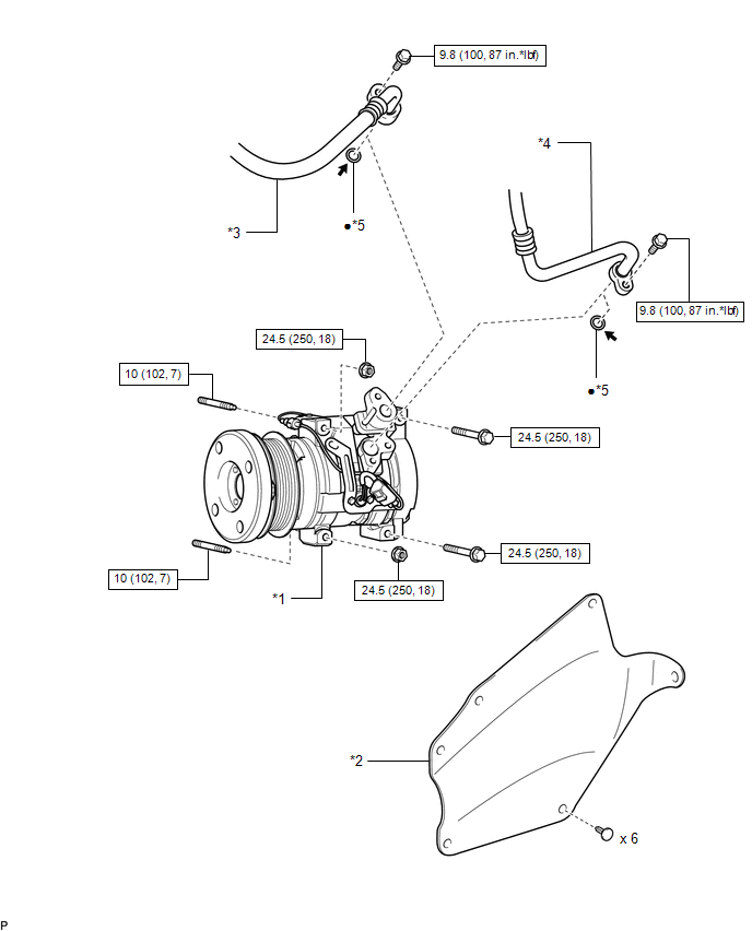
ILLUSTRATION 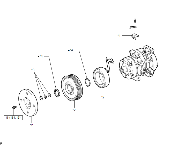
|
Toyota Tundra Service Manual > Engine Coolant Temperature Sensor: Inspection
INSPECTION PROCEDURE 1. INSPECT ENGINE COOLANT TEMPERATURE SENSOR (a) Partially immerse the sensor in water and warm up the water. (b) Measure the resistance according to the value(s) in the table below. Standard Resistance: Tester Connection Condition Specified Condition 1 - 2 Approx. 20°C (68°F) ...


