INSTALLATION PROCEDURE 1. ADJUST COMPRESSOR OIL (a) When replacing the compressor and magnetic clutch with a new one, gradually discharge the refrigerant gas from the service valve, and drain the following amount of oil from the new compressor and magnetic clutch before installation. Standard: (Oil capacity inside the new compressor and magnetic clutch: 140 to 155 cc (4.73 to 5.24 fl.oz)) - (Remaining oil amount in the removed compressor and magnetic clutch) = (Oil amount to be removed from the new compressor when replacing) NOTICE:
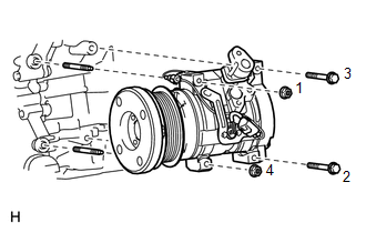
2. INSTALL COOLER COMPRESSOR ASSEMBLY
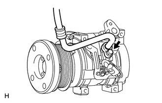
(b) Install the 2 bolts and 2 nuts. Torque: 24.5 N·m {250 kgf·cm, 18 ft·lbf} HINT: Tighten the bolts and nuts in the order shown in the illustration to install the cooler compressor assembly. (c) Connect the connector. 3. CONNECT NO. 1 COOLER REFRIGERANT SUCTION HOSE (a) Remove the attached vinyl tape from the No. 1 cooler refrigerant suction hose. (b) Sufficiently apply compressor oil to a new O-ring and the fitting surface of the cooler compressor assembly. Compressor oil: ND-OIL 12 or equivalent (c) Install the O-ring to the No. 1 cooler refrigerant suction hose.
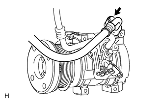
4. CONNECT NO. 1 COOLER REFRIGERANT DISCHARGE HOSE (a) Remove the attached vinyl tape from the No. 1 cooler refrigerant discharge hose. (b) Sufficiently apply compressor oil to a new O-ring and the fitting surface of the cooler compressor assembly. Compressor oil: ND-OIL 12 or equivalent (c) Install the O-ring to the No. 1 cooler refrigerant discharge hose.
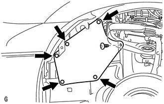
5. INSTALL FAN AND GENERATOR V BELT (a) for 1UR-FE: Click here (b) for 3UR-FE: Click here (c) for 3UR-FBE: Click here 6. INSTALL FRONT FENDER APRON SEAL LH
7. CHARGE REFRIGERANT (for HFC-134a(R134a)) Click here 8. CHARGE AIR CONDITIONING SYSTEM WITH REFRIGERANT (for HFO-1234yf(R1234yf)) Click here 9. WARM UP ENGINE (a) for HFC-134a(R134a): Click here (b) for HFO-1234yf(R1234yf): Click here 10. CHECK FOR REFRIGERANT GAS LEAK (for HFC-134a(R134a)) Click here 11. INSPECT FOR REFRIGERANT LEAK (for HFO-1234yf(R1234yf)) Click here |
Toyota Tundra Service Manual > Air Conditioning System(for Automatic Air Conditioning System): Customize Parameters
CUSTOMIZE PARAMETERS 1. CUSTOMIZING FUNCTION WITH TECHSTREAM NOTICE: When the customer requests a change in a function, first make sure that the function can be customized. Be sure to make a note of the current settings before customizing. When troubleshooting a function, first make sure that the fu ...