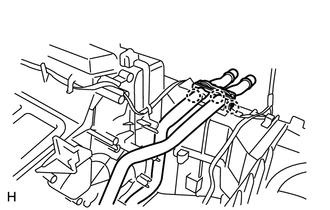
REMOVAL PROCEDURE 1. REMOVE AIR CONDITIONING UNIT (See page 2. REMOVE NO. 3 AIR DUCT SUB-ASSEMBLY
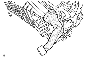
3. REMOVE AIR CONDITIONING AMPLIFIER ASSEMBLY
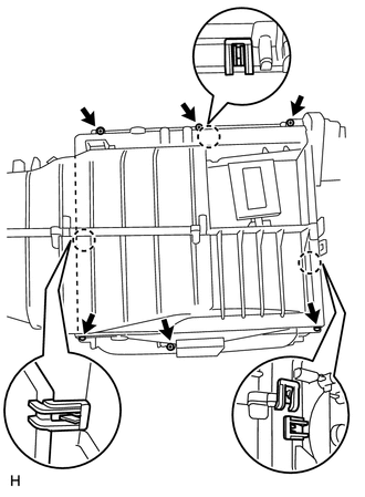
4. REMOVE BLOWER ASSEMBLY
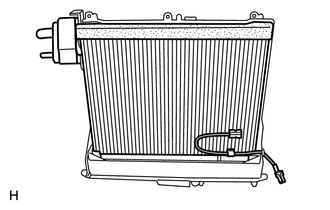
5. REMOVE NO. 1 COOLER EVAPORATOR SUB-ASSEMBLY
6. REMOVE NO. 1 COOLER THERMISTOR
|
Toyota Tundra Service Manual > Lighting: Headlight Relay
On-vehicle Inspection ON-VEHICLE INSPECTION PROCEDURE 1. INSPECT HEADLIGHT RELAY (a) Remove the headlight relay from the engine room relay box. (b) Check the resistance. (1) Measure the resistance according to the value(s) in the table below. Standard Resistance: Tester Connection Condition Specifie ...