Components COMPONENTS ILLUSTRATION 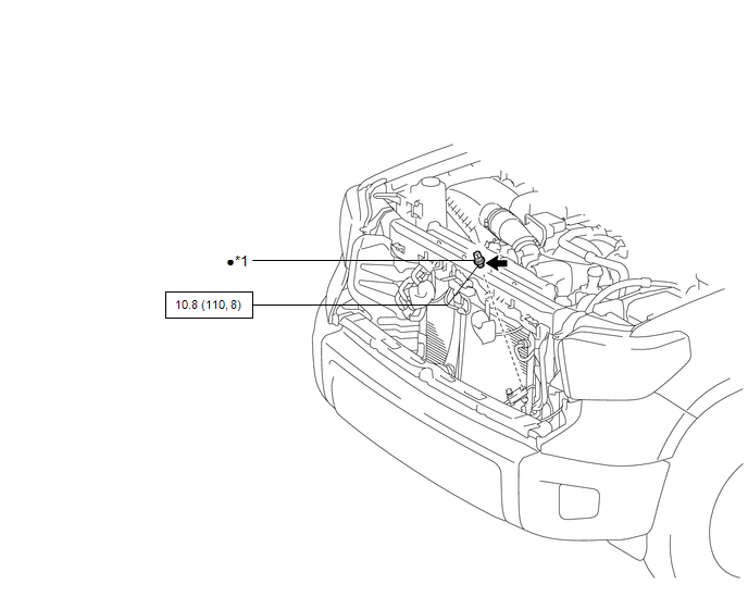
Installation INSTALLATION PROCEDURE 1. INSTALL PRESSURE SWITCH
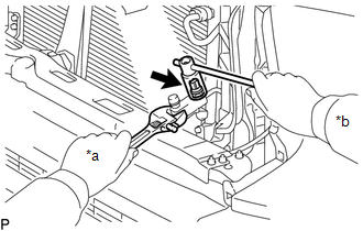
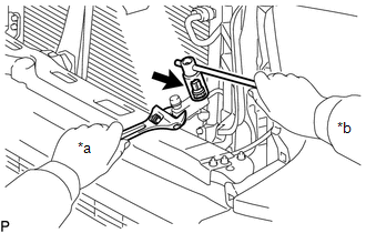
(b) Using a 27 mm deep socket wrench, install the pressure switch. Torque: 10.8 N·m {110 kgf·cm, 8 ft·lbf} (c) Connect the connector. 2. CHARGE REFRIGERANT (for HFC-134a(R134a)) Click here 3. CHARGE AIR CONDITIONING SYSTEM WITH REFRIGERANT (for HFO-1234yf(R1234yf)) Click here 4. WARM UP ENGINE (a) for HFC-134a(R134a): Click here (b) for HFO-1234yf(R1234yf): Click here 5. CHECK FOR REFRIGERANT GAS LEAK (for HFC-134a(R134a)) Click here 6. INSPECT FOR REFRIGERANT LEAK (for HFO-1234yf(R1234yf)) Click here 7. INSTALL RADIATOR GRILLE SUB-ASSEMBLY Click here Removal REMOVAL PROCEDURE 1. REMOVE RADIATOR GRILLE SUB-ASSEMBLY Click here 2. RECOVER REFRIGERANT FROM REFRIGERATION SYSTEM (a) for HFC-134a(R134a): Click here (b) for HFO-1234yf(R1234yf): Click here 3. REMOVE PRESSURE SWITCH
(b) Using a 27 mm deep socket wrench, remove the pressure switch. NOTICE: Seal the openings of the disconnected parts using vinyl tape to prevent moisture and foreign matter from entering them. |
Toyota Tundra Service Manual > Front Propeller Shaft Assembly: Installation
INSTALLATION PROCEDURE 1. INSTALL FRONT PROPELLER SHAFT (a) Completely remove any oil or the like and clean the contact surfaces of the propeller shaft flange, differential flange and transfer flange. (b) for Front Differential Side: (1) Align the matchmarks on the differential and propeller shaft f ...