INSPECTION PROCEDURE 1. INSPECT FRONT DOOR LOCK ASSEMBLY LH (a) Check the door lock motor. (1) Apply battery voltage to the door lock motor and check operation of the door lock motor. 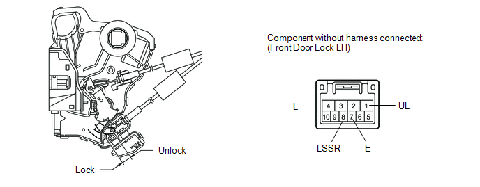
OK:
(b) Check the door lock position switch. (1) Measure the resistance according to the value(s) in the table below. Standard resistance:
(c) Check the door lock and unlock switch. (1) Measure the resistance according to the value(s) in the table below. 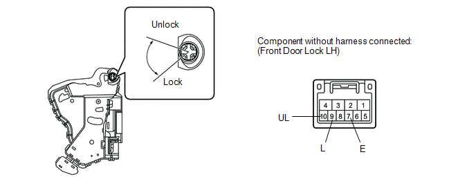
Standard resistance:
2. INSPECT FRONT DOOR LOCK ASSEMBLY RH (a) Check the door lock motor. (1) Apply battery voltage to the door lock motor and check operation of the door lock motor. 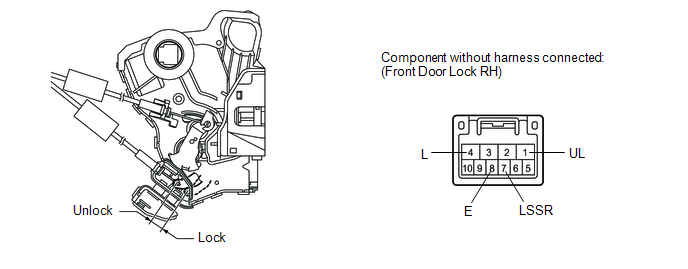
OK:
(b) Check the door lock position switch. (1) Measure the resistance according to the value(s) in the table below. Standard resistance:
|
Toyota Tundra Service Manual > Satellite Radio Tuner(for Column Shift Type): Removal
REMOVAL PROCEDURE 1. PRECAUTION NOTICE: After turning the ignition switch off, waiting time may be required before disconnecting the cable from the battery terminal. Therefore, make sure to read the disconnecting the cable from the battery terminal notice before proceeding with work (See page ). 2. ...


