
SYSTEM DIAGRAM 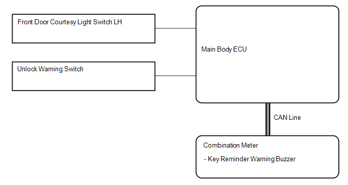 Communication table: Communication table:
|
Toyota Tundra Service Manual > Navigation System: Sound Signal Circuit between Navigation Receiver Assembly and Stereo Jack Adapter
DESCRIPTION The No. 1 stereo jack adapter assembly sends the sound signal from an external device to the navigation receiver assembly via this circuit. The sound signal that has been sent is amplified by the navigation receiver assembly, and then is sent to the speakers. If there is an open or short ...


