Components COMPONENTS ILLUSTRATION 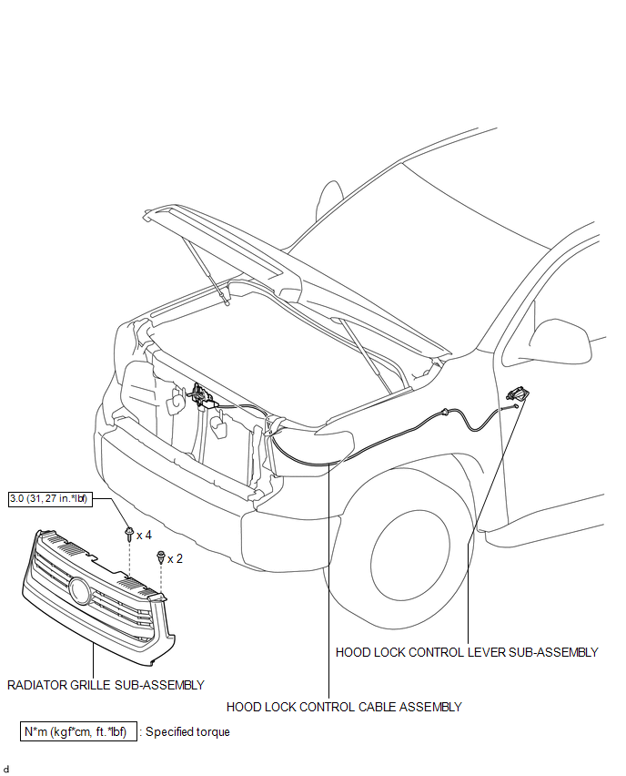
ILLUSTRATION 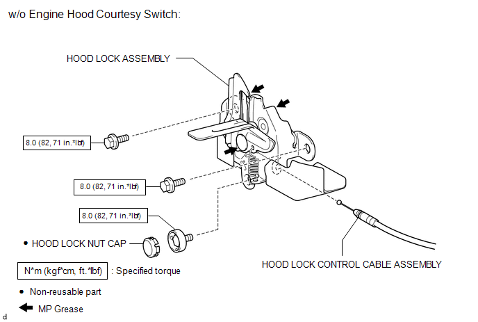
ILLUSTRATION 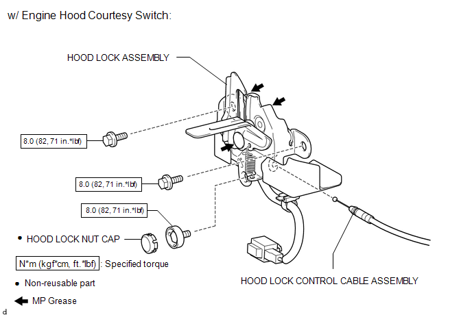
Installation INSTALLATION CAUTION / NOTICE / HINT HINT: A bolt without a torque specification is shown in the standard bolt chart (See
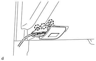
page PROCEDURE 1. INSTALL HOOD LOCK CONTROL CABLE ASSEMBLY (a) Pass the hood lock control cable assembly into the engine room. (b) Pass the rear end of the hood lock control cable assembly through the grommet until the cable stopper is attached to the grommet. (c) Pass the front end of the hood lock control cable assembly through the upper radiator support. (d) Attach the hood lock control cable assembly to the clamps as shown in the illustration.  Text in Illustration Text in Illustration
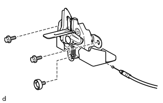
2. INSTALL HOOD LOCK CONTROL LEVER SUB-ASSEMBLY (a) Connect the hood lock control cable assembly to the hood lock control lever sub-assembly. (b) Attach the 3 claws to install the hood lock lever sub-assembly. 3. INSTALL HOOD LOCK ASSEMBLY (a) Apply MP grease to the sliding areas of the hood lock assembly. 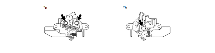 Text in Illustration Text in Illustration
(b) Connect the hood lock control cable assembly. (c) Install the hood lock assembly. (d) Install the 2 bolts and hood lock bolt. Torque: 8.0 N·m {82 kgf·cm, 71 in·lbf} (e) Install a new hood lock nut cap. (f) w/ Engine Hood Courtesy Switch: (1) Connect the connector. (2) Attach the clamp. 4. INSTALL RADIATOR GRILLE SUB-ASSEMBLY
Removal REMOVAL PROCEDURE 1. REMOVE RADIATOR GRILLE SUB-ASSEMBLY
2. REMOVE HOOD LOCK ASSEMBLY 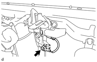
(a) w/ Engine Hood Courtesy Switch: (1) Disconnect the connector. (2) Detach the clamp.
(d) Remove the hood lock assembly. (e) Disconnect the hood lock control cable assembly. 3. REMOVE HOOD LOCK CONTROL LEVER SUB-ASSEMBLY
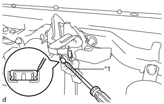
(b) Disconnect the hood lock control cable assembly and remove the hood lock control lever sub-assembly. 4. REMOVE HOOD LOCK CONTROL CABLE ASSEMBLY (a) Using a screwdriver, detach the hood lock control cable assembly from the clamps as shown in the illustration. HINT: Tape the screwdriver tip before use. (b) Pull the hood lock control cable assembly from the engine room and remove it. 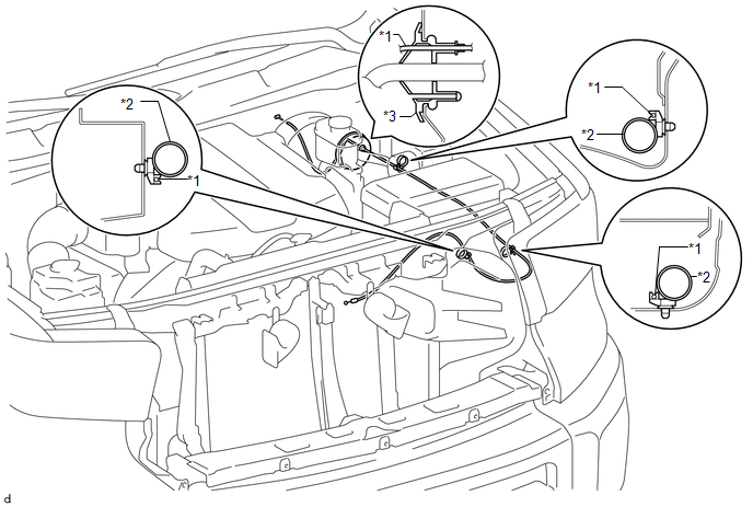 Text in Illustration Text in Illustration
|
Toyota Tundra Service Manual > Sfi System: Brake Switch "B" Circuit High (P0724)
DESCRIPTION The purpose of this circuit is to prevent the engine from stalling while driving in the lock-up condition when the brakes are suddenly applied. When the brake pedal is depressed, this switch sends a signal to the ECM. Then the ECM cancels the operation of the lock-up clutch while braking ...

 ).
).