DISASSEMBLY CAUTION / NOTICE / HINT HINT:
PROCEDURE 1. PRECAUTION NOTICE: After turning the ignition switch off, waiting time may be required before disconnecting
the cable from the battery terminal. Therefore, make sure to read the disconnecting
the cable from the battery terminal notice before proceeding with work (See page
2. DISCONNECT CABLE FROM NEGATIVE BATTERY TERMINAL CAUTION: Wait at least 90 seconds after disconnecting the cable from the negative (-) battery terminal to prevent airbag and seat belt pretensioner activation. 3. REMOVE REAR DOOR INSIDE HANDLE BEZEL PLUG LH
4. REMOVE REAR UPPER DOOR ARMREST BASE PANEL LH
5. REMOVE REAR POWER WINDOW REGULATOR SWITCH ASSEMBLY
6. REMOVE REAR DOOR FRAME GARNISH LH
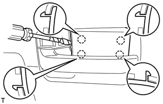
7. REMOVE REAR DOOR ARMREST COVER LH 8. REMOVE REAR DOOR TRIM BOARD SUB-ASSEMBLY LH
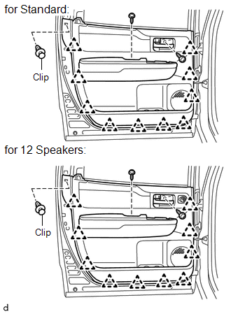
(b) Using a clip remover, remove the clip. (c) for Standard: (1) Detach the 10 clips and remove the trim board. (d) for 12 Speakers: (1) Detach the 10 clips and remove the trim board. Then disconnect the connector.
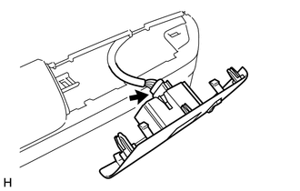
(f) Remove the inside handle. 9. REMOVE REAR NO. 2 SPEAKER ASSEMBLY (for 12 Speakers)
10. REMOVE REAR INNER DOOR GLASS WEATHERSTRIP LH 11. REMOVE REAR NO. 2 DOOR TRIM BRACKET
12. REMOVE REAR SPEAKER ASSEMBLY
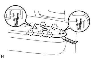
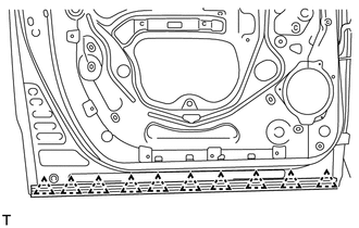
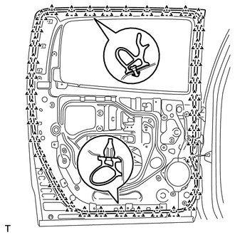
13. REMOVE REAR DOOR SERVICE HOLE COVER LH
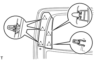
(b) Remove the rear door service hole cover. HINT: Remove the remaining tape on the door. 14. REMOVE REAR DOOR GLASS RUN LH
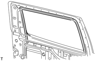
15. REMOVE REAR DOOR REAR LOWER WINDOW FRAME SUB-ASSEMBLY LH
16. REMOVE REAR DOOR GLASS SUB-ASSEMBLY LH 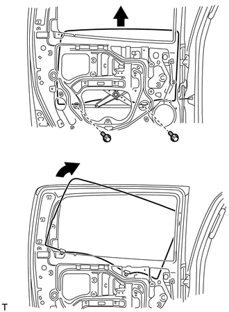
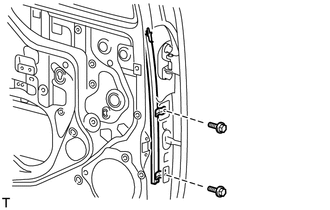
(a) Temporarily install the power window regulator switch. (b) Move the door glass until the bolts appear in the service holes. (c) Remove the 2 bolts. NOTICE: Be careful when removing the bolts as the glass may fall and become damaged. (d) Remove the rear door glass from the rear door window regulator as shown in the illustration. NOTICE: Do not damage the door glass. (e) Remove the power window regulator switch. 17. REMOVE REAR DOOR FRONT WINDOW GUIDE SUB-ASSEMBLY LH
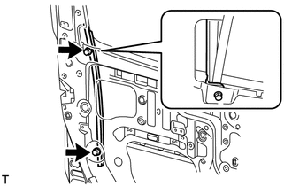
18. REMOVE REAR NO. 2 DOOR GLASS RUN LH (a) Remove the rear door glass run from the rear front lower door window guide. 19. REMOVE REAR OUTER DOOR GLASS WEATHERSTRIP
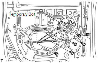
20. REMOVE REAR DOOR WINDOW REGULATOR SUB-ASSEMBLY LH
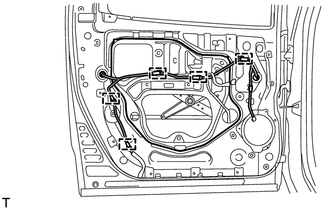
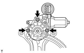
(b) Loosen the temporary bolt. NOTICE: Do not remove the temporary bolt. If the temporary bolt is removed, the front door window regulator may fall and become damaged. (c) Remove the 5 bolts and window regulator. (d) Remove the window regulator through the service hole. (e) Remove the temporary bolt from the door window regulator. 21. REMOVE POWER WINDOW REGULATOR MOTOR ASSEMBLY LH
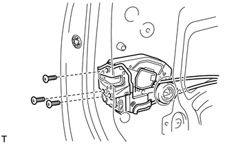
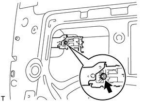
22. REMOVE REAR DOOR LOCK ASSEMBLY LH
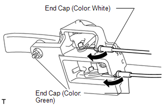
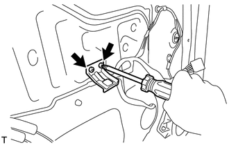
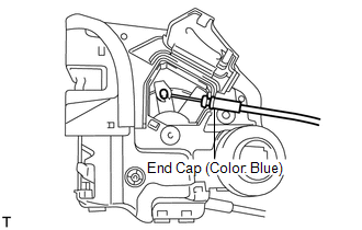
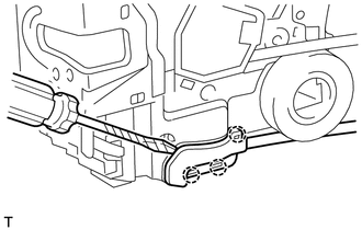
(b) Using a T30 "TORX" wrench, remove the 3 screws and door lock. HINT: Remove the door lock through the service hole. NOTICE: Be careful when removing the bolts as the door lock may fall and become damaged. 23. REMOVE REAR DOOR LOCK REMOTE CONTROL CABLE ASSEMBLY LH
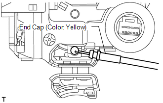
24. REMOVE REAR DOOR INSIDE LOCKING CABLE ASSEMBLY LH
25. REMOVE REAR DOOR LOCK CHILD PROTECTION COVER LH 26. REMOVE REAR DOOR OUTSIDE HANDLE COVER LH
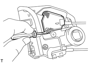
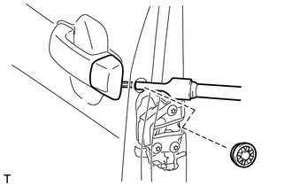
(b) Using a T30 "TORX" wrench, loosen the screw and remove the rear door outside handle cover. (c) Remove the cover. 27. REMOVE REAR DOOR OUTSIDE HANDLE ASSEMBLY LH
28. REMOVE REAR DOOR OUTSIDE HANDLE FRAME SUB-ASSEMBLY LH
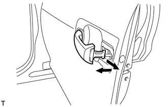
(b) Using a T30 "TORX" wrench, loosen the screw. (c) Slide the outside handle frame to remove it. HINT: Remove the outside handle frame through the service hole. 29. REMOVE REAR DOOR LOCK OPEN ROD LH (a) Remove the lock open rod from the outside handle frame. 30. REMOVE REAR NO. 2 DOOR WEATHERSTRIP LH
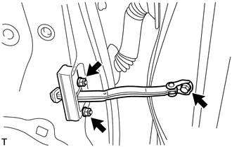
31. REMOVE REAR DOOR CHECK ASSEMBLY LH
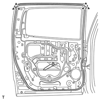
32. REMOVE REAR DOOR WEATHERSTRIP LH
|
Toyota Tundra Service Manual > Front Power Seat Control System(w/ Memory): Initialization
INITIALIZATION 1. INITIALIZE FRONT POWER SEAT CONTROL SYSTEM NOTICE: The position sensor initialization must be performed if one of the following occurs. The position control ECU and switch assembly is replaced. The front seat cushion frame sub-assembly LH is inspected or replaced. The front seatbac ...