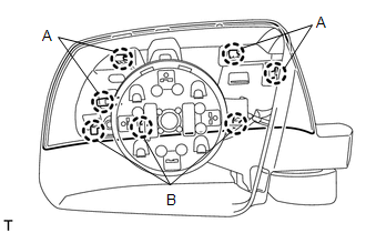
REMOVAL CAUTION / NOTICE / HINT HINT:
PROCEDURE 1. REMOVE FRONT DOOR INSIDE HANDLE BEZEL PLUG
2. REMOVE FRONT UPPER ARMREST BASE PANEL LH
3. REMOVE FRONT LOWER DOOR FRAME BRACKET GARNISH
4. REMOVE FRONT DOOR TRIM BOARD SUB-ASSEMBLY
5. REMOVE OUTER REAR VIEW MIRROR ASSEMBLY 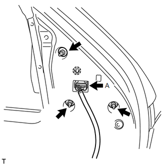
(a) w/ Power Mirror Control System: Disconnect the connector labeled A. (b) Remove the 3 nuts. (c) Detach the claw and remove the outer rear view mirror assembly. 6. REMOVE OUTER REAR VIEW MIRROR SUB-ASSEMBLY
7. REMOVE OUTER MIRROR LIGHT ASSEMBLY LH (for Standard)
8. REMOVE OUTER MIRROR COVER (for Standard)
(b) Slightly lift up the cover to detach the 3 claws labeled B and remove the outer mirror cover. 9. REMOVE SIDE TURN SIGNAL LIGHT LENS (for Extended Type) 10. REMOVE OUTER MIRROR COVER LH (for Extended Type) 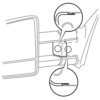
(a) Detach the 2 claws and remove the outer mirror cover LH. |
Toyota Tundra Service Manual > Name Plate: Removal
REMOVAL PROCEDURE 1. REMOVE FRONT FENDER PLATE LH HINT: When removing the front fender plate LH, heat the vehicle body and front fender plate LH using a heat light. Standard: Item Temperature Vehicle Body 40 to 60°C (104 to 140°F) Front Fender Plate LH 20 to 30°C (68 to 86°F) NOTICE: Do not heat ...