Components COMPONENTS ILLUSTRATION 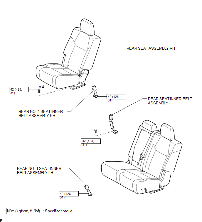
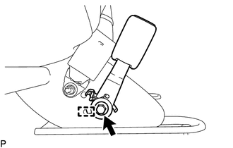
Installation INSTALLATION PROCEDURE 1. INSTALL REAR NO. 1 SEAT INNER BELT ASSEMBLY LH (a) Attach the guide. (b) Tighten the bolt to install the rear No. 1 seat inner belt assembly LH. Torque: 42 N·m {428 kgf·cm, 31 ft·lbf}
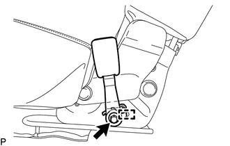
2. INSTALL REAR NO. 1 SEAT INNER BELT ASSEMBLY RH (a) Attach the guide. (b) Tighten the bolt to install the rear No. 1 seat inner belt assembly RH. Torque: 42 N·m {428 kgf·cm, 31 ft·lbf}
3. INSTALL REAR SEAT INNER BELT ASSEMBLY
(b) Install the rear seat inner belt assembly with the bolt. Torque: 42 N·m {428 kgf·cm, 31 ft·lbf} NOTICE:
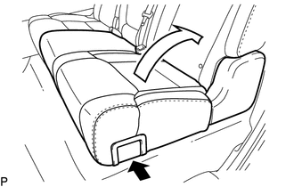
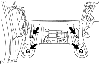
(c) Install the rear seat assembly RH with the 4 bolts. Torque: 42 N·m {428 kgf·cm, 31 ft·lbf}
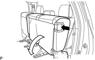
Removal REMOVAL PROCEDURE 1. REMOVE REAR NO. 1 SEAT INNER BELT ASSEMBLY LH
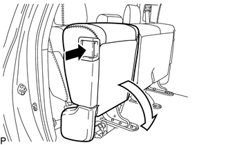
(c) Detach the guide and remove the rear No. 1 seat inner belt assembly LH. 2. REMOVE REAR NO. 1 SEAT INNER BELT ASSEMBLY RH
(c) Detach the guide and remove the rear No. 1 seat inner belt assembly RH. 3. REMOVE REAR SEAT INNER BELT ASSEMBLY
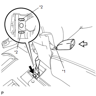
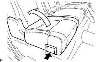
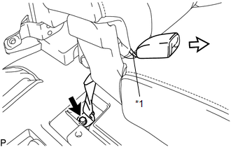
(d) Pass the rear seat inner belt assembly through the rubber band of the separate type rear seatback cover in the direction indicated by the arrow shown in the illustration, and then remove the rear seat inner belt assembly. Text in Illustration
|
Toyota Tundra Service Manual > Power Window Control System(w/o Jam Protection Function): Operation Check
OPERATION CHECK 1. CHECK WINDOW LOCK SWITCH (a) Check that the front passenger side power window and rear power windows cannot be operated when the window lock switch of the master switch is pressed. OK: Operation of front passenger side power window and rear power windows are disabled. (b) Check th ...